


– 32 –
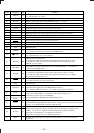
Pin No. Pin Name I/O Function
37 AMP ON O
Standby on/off control signal output to the power amplifier (IC751)
“L”: standby mode, “H”: amp on
38 PLL-CKO O
PLL serial data transfer clock signal output to the FM/AM PLL (IC21)
39 PLL-CE O
PLL chip enable signal output to the FM/AM PLL (IC21) “H” active
40 PLL-SO O
PLL serial data output to the FM/AM PLL (IC21)
41 PLL-SI I
PLL serial data input from the FM/AM PLL (IC21)
42 LCD-SO
O Serial data output to the liquid crystal display driver (IC901)
43 LCD-CE
O Chip enable signal output to the liquid crystal display driver (IC901) “H” active
44 LCD-CKO
O Serial data transfer clock signal output to the liquid crystal display driver (IC901)
45 VOL-SIO I/O
Two-way data bus with the electrical volume (IC331)
46
NCO
O
Not used (open)
47 VOL-CKO O
Bus clock signal output to the electrical volume (IC331)
48 ACC-IN
I Accessory detect signal input terminal “L”: accessory on
49 MUT
O Audio line muting on/off control signal output terminal “H”: muting on
50
NCO
O
Not used (open)
51 AMSON O
Tape auto music sensor control signal output to the CXA2509AQ (IC301)
“L” is output to lower the gain for audio level at FF/REW mode
52 N/R-OUT O
Forward/reverse direction control signal output to the CXA2509AQ (IC301)
“L”: forward direction, “H”: reverse direction
53 MTLON I/O
METAL control in/out terminal
At initial mode: valid/invalid selection input of METAL function (valid at “L” input)
At normal mode: METAL on/off control signal output to the CXA2509AQ (IC301)
(METAL on at “H” output)
54 TAPE-MUT O
Tape muting on/off control signal output to the CXA2509AQ (IC301) “H”: muting on
Active at ATA, FF/REW mode
55 DOLON I/O
Dolby control in/out terminal
At initial mode: valid/invalid selection input of dolby function (valid at “L” input)
At normal mode: dolby on/off control signal output terminal (dolby on at “H” output)
Not used this function (fixed at “H”)
56 AMSIN I
Whether a music is present or not from CXA2509AQ (IC301) is detected at auto music sensor
“L”: music is present, “H”: music is not present
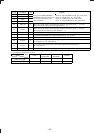
57 to 75
NCO
O
Not used (open)
76 ST-MONO I/O
FM stereo broadcasting detection signal input from the FM/AM tuner unit (TU1), or forced
monaural control signal output to the FM/AM tuner unit (TU1)
“L” is input in the FM stereo mode, or “L” is output in the forced monaural mode
77 SD-IN
I
Station detector detect input from the FM/AM tuner unit (TU1)
Stop level for SEEK, BTM, etc. is determined SD is present at input of “H”
78 RE-IN0
I
79 RE-IN1
I
80 AD-ON
O
A/D converter power control signal output terminal
When the KEYACK (pin @§) that controls reference voltage power for key A/D conversion input
is active, “L” is output from this terminal to enable the input
81 POWSEL
I Power select switch (S501) input terminal “L”: off (halt mode), “H”: on (operation mode)
82
ILL-ON O
83 REEL I
Rotation detect signal input from supply reel sensor and take-up reel sensor on the deck
mechanism
Power on/off control signal output of the illumination LED and liquid crystal display driver
(IC901) “H”: power on Depends on initial setting of power select switch (S501)
Power select switch (S501) on: “H” output at the accessory on
Power select switch (S501) off: “H” output at the power on
Dial pulse input of the rotary encoder (RE900)
(for VOLUME/BASS/TREBLE/BALANCE/FADER control)