


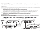

Parallel Wiring
Series Wiring
A x B
A + B
= R
Equation
A
B
R
A + B= R
Equation
A
B
R
(A x B)(C x D)
(A + B) + (C + D)
Parallel Wiring, Dual Voice Coil
Series/Parallel Wiring Dual Voice Coil
R
R
A
B
CD
ABC
D
(A + B) x (C + D)
A + B + C + D
= R
Equation
=R
Equation
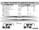
The BMF1000D and the BMF600D will reach their potential output into a 1ohm load. However, a lower impedance can send the amplifier into current
protection and possibly damage the circuitry. To prevent damage, use the following formulas to help you figure out the load you are placing on the
amplifier. If you have any difficulties, please contact your local Crossfire dealer or Crossfire's Technical Assistance at 562-483-8111.
Impedance Equations
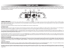
LOW IN
R
L
LEVEL
HPF FULL LPF
OFF ON
MASTER
IN
OUT
INVERT
SUB
SONIC
50 250
LPF
LINE OUT
REMOTE
CROSS
OVER
SLAVE 0 180
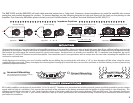
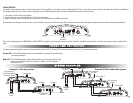
Appropriate mounting is very important for prolonged life expectancy of any amplifier. Select a location of applicable space that allows sufficient airflow and provides
protection from moisture. Keep in mind that an amplifier should never be mounted upside down. Upside down mounting will compromise heat dissipation through
the heatsink and will engage the thermal protection circuit much sooner. Excessive heat can shorten your amplifier's life. To maximize heat dissipation, be sure to
leave at least 2.5 inches of clearance around the amplifier. Fans should be used in correspondence with an escape duct for heat when mounting the amplifier in an
enclosed or restricted area.
Avoid slipping and scratching your new Crossfire amplifier by pre-drilling the mounting holes with either a 1/8" or 3mm diameter drill bit when using the screws
supplied in the accessory kit. Always investigate the mounting area thoroughly for electrical wires, vacuum lines, and brake or fuel lines before you start to prevent any
potentially expensive mistakes.
MOUNTING
MOUNTING
Heat is trapped inside the amplifier, shortening
the life of the electronic components.
x
Incorrect Mounting
Correct Mounting
O
Heat is lifted from the amplifier heatsink.
All Crossfire amplifiers are designed to work within 10.5 to 16 volts DC. Therefore, as a precaution the vehicle's electrical system should be checked for correct voltage
supply with the help of a voltmeter. First, connect the test leads of the voltmeter to the battery terminals with the ignition in of the vehicle in the off position. The
voltmeter should read no less than 12 volts. Next check the voltage of the battery with the engine running between 1500 and 2000 rpms. The voltmeter should now
read between 13.5 and 14.5 volts. If your vehicle's electrical is not up to these specifications, we recommend having it checked by an automotive mechanic before
you further the installation.
POWER CONNECTIONS
POWER CONNECTIONS
LOW IN
R
L
LEVEL
HPF FULL LPF
OFF ON
MASTER
IN
OUT
INVERT
SUB
SONIC
50 250
LPF
LINE OUT
REMOTE
CROSS
OVER
SLAVE 0 180
2