


CONNECTING OUTPUT TRANSFORMERS:
For basic model, the output transformers should be designed to provide 5kΩ primary resistance.
For the full pack, the primary resistance should have 2.5kΩ rating. Rating of the secondary
winding should correspond to the impedance of your speakers (4, 8 or 16Ω, typically). There are
many transformers in the market that have multiple taps to accommodate various combinations.
Power rating should be minimum 3W for basic and 6W for full-pack configuration.
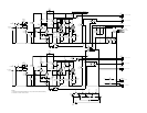
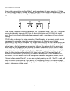
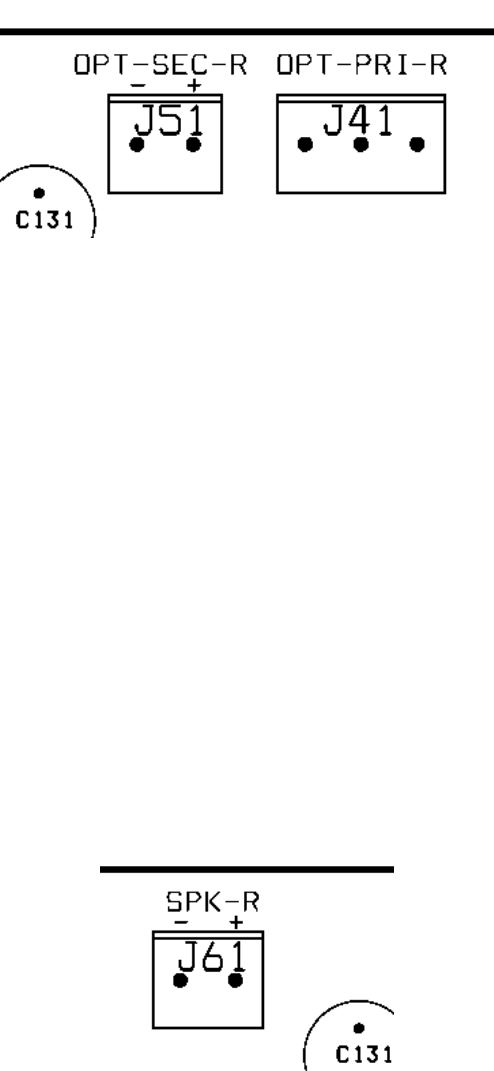
Model 1 features two pairs of terminals for connecting output transformers. The terminals are J41
and J51 for the right channel transformer and J42, J52 for the left channel. The terminal blocks for
the right channel connections are shown below.
.
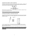
Output transformer’s primary winding is connected to the two end terminals of J41. Right side
terminal of the J41, as shown on the picture above, is connected to +Va, and the left end is
connected to the plate of the pentode part of PCL82. Middle terminal is used for the ultralinear
connection if the transformer has the UL tap.
Left channel transformer is connected the same way using J42.
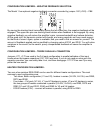
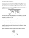
Transformer’s secondary winding is connected to J51 (J52 for the left channel). Terminal with
minus sign is connected to the system ground.
It is important that both, left and right output transformers are connected identically, which will
ensure that both channels operate in phase and provide adequate stereo picture.
If the negative feedback is to be used, it is also important that the primary and secondary are
connected in phase, so please carefully check transformer documentation. An oscilloscope is
valuable tool if you use old, second hand transformers which may not have adequate markings.
CONNECTING SPEAKERS:
Speakers’ impedance should match rated secondary impedance of the output transformer.
Speakers are connected to terminals J61 (right speaker) and J62 (left speaker).
14