


99-7102-100 1/05
1493 Bentley Drive • Corona, CA 92879 • 951-272-1996 • 800-624-7960 • Fax 951-272-1584
www.vizualogic.com
Copyright © 2005 TMI Products, Inc.
All Rights Reserved
OVERHEAD VIDEO SYSTEM
with ThinDVD CAPABILITY
Installation Manual
Quantum
™
Series
Section IV – Overhead Installation
NOTE: Depending on the vehicle, permanent modifications to the vehicle may be necessary to
allow the installation of the Quantum Series Overhead and its related hardware. Professional
installation is strongly recommended.
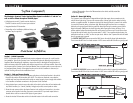
1. Align the mounting bracket to the desired mounting location, ensuring that the mounting
holes line up with the vehicle’s roof cross member. Verify that the mounting hardware (the
included sheet metal screws, or otherwise) will not pierce the outer skin of the vehicle once
the bracket is mounted. Carefully secure the bracket to the vehicle’s roof cross member,
making sure not to pinch the previously routed cables.
NOTE: If a ThinDVD player is not being installed at this time, proceed to step #4.
2. To install the optional ThinDVD player, carefully route the dome light wiring and the main
system cable through the opening in the ThinDVD player. Loosely fasten the ThinDVD player
to the mounting bracket with the supplied machine screws.
3. Before completely tightning down the ThinDVD player make sure to push all the excess cable
back into the headliner leaving about six inches availible. Tighten down the ThinDVD mount-
ing screws making sure not to overtighten and distort the shape of the ThinDVD player.
4. Connect the dome light wiring harness, main system cable, modulator cable, and the
ThinDVD din cable (if applicable) to the Quantum Series Overhead Monitor.
5. Carefully raise the Quantum Series Overhead into place, making sure not to pinch any of the
system cables.
6. Mount the Quantum Series Overhead Monitor to the mounting bracket with the
supplied machine screws. Do not overtighten!
Section V – Connecting System Power.
Plug the included in-line power filter to the main system cable and connect the power leads to
12V+ and 12V ground. The wires are color coded as follows:
Red = 12+VDC Constant Power
Yellow = 12+VDC Switched Power
Black = Ground