


Visor Installation
1. Disconnect the vehicle’s negative battery terminal. (Black wire)
2. Remove the screws holding the passenger side sunvisor brackets and unplug
any wires that may be connected to the visor pivot.
3. Remove the secondary (smaller) visor from the mounting.
4. Slide the Vizualogic Visor Video into the mounting brackets.
5. Remove the “A” pillar trim and kick panel on the passenger side and route the
Video Cable through the hole in the headliner for the visor mounting bracket
near the top of the “A” pillar.
6. Re-install the visors and mounting brackets to the headliner.
7. Route the Video Cable down the “A” pillar. Use a wire fish to pull the cable
straight down the edge of the vehicle’s dash to the kick panel
8. From behind the kick panel, attach the secondary cable/relay assembly to the
cable you just routed.
9. Route the black wire from the relay to the parking brake switch and connect
with the supplied connector.
(2) Batteries, AAA
(1) VL8000 Installation Manual
(1) VL8000 Owner’s Manual
VL8000 Kit contents:
(1) Visor with Monitor and Cable
(1) A/V Module
(1) 12V Harness for A/V Module
(1) Remote Control
12V Power Installation
We recommend the installation of a main power switch for the entire headrest system.
The circuit should be marked to assist the consumer in locating the correct vehicle fuse
for the video system in the case of a system failure.
AV Module Installation
1. Place A/V module in a well protected area under a seat or behind a panel.
2. Connect the 12V harness to the same 12V+ and 12V Ground as the Video Source Unit(s).
3. Insert 12V harness connector into A/V module.
4. Insert video cable from Source.
5. Insert video output cable connecting the Headrest.
6. Install I/R extender cable from source unit to A/V module.
System Operation
Please see CONTROLS on page 4, 5 and 6 of the VL8000 Owner’s Manual for system
operation instructions.
Sp ecifications
ELECTRICAL SPECIFICATIONS – 7.0”
Display Type: LCD
Screen size: 7.0” (Diagonal)
Resolution: 1,440 (W) x 234 (H)
Number of Pixels: 336,960
Brightness: 400 nit
Horizontal view angle: ±60°
Vertical view angle: +60°, -30°
Power requirement: (Monitor) DC 12.0V ±1.5
Power consumption: (Monitor) DC <1A (app.7mA at 10.5 volts)
Note: Designs and specifications are subject to change without notice and without
legal obligation.
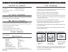
Compression Spring Modification Instructions
4. Reinstall the compression springs onto the visor mounting brackets. It may be
necessary to use a screwdriver to guide the spring onto the spring stop on the
inside radius of the mounting brackets.
1. Remove visor
brackets from
vehicle.
2. Pry off the spring
clip using a flat
blade screw driver.
3. Use pliers to compress
the springs until the
opening is 1/8˝.