


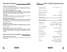
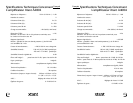
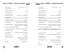
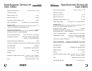

Xtant A4004 Specifications
Frequency Response: 20 Hz to 20 kHz +/– 1 dB
Number of Channels: 4
Watts per Channel @ 4Ω: 4 x 50
Watts per Channel @ 2Ω: 4 x 100
Bridged Mono @ 4Ω: 2 x 200
Recommended Load: ≥2Ω Stereo / ≥4Ω Bridged
Distortion (THD): ≤ .2%
Measured: 20 Hz to 20 kHz at rated power, all channels driven 4Ω
Signal to Noise Ratio: ≥ 100 dB
Measured: A-weighted in 20 kHz noise bandwidth @ 1 volt sensitivity
Damping Factor: ≥ 200 @ 100 Hz with 4Ω load
Input Sensitivity: 100 mV to 8.5 V RMS Unbalanced
200 mV to 17 V RMS Balanced
Input to Line Output Gain: 0 dB
On-Board Crossover: Front: 12dB HP, 40-120 Hz
Rear: 12dB HP or 24dB Mono LP, 40-120 Hz
Balanced Line: On Board
Power Supply: Fully Regulated, PWM
Operational Voltage: 10 to 16 Volts
Fusing Requirement: 60 Amp
Size (L xW x H): 15-13/16” x 9-1/4” x 1-7/8”
402mm x 235mm x 47mm
A.R.C.: 0-15dB Level Adjustment
Bass Boost: 0-12dB @ 45 Hz
Warranty: Limited 4 Year Parts and Labor
(see page 8 for details)
English
6 7
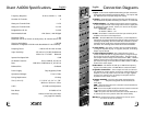
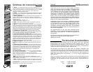
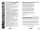
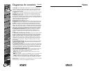
Connection Diagrams
1. Input – Xtant A series amplifiers feature RCA type input connections.
Source units with an output signal level of 100mV – 17V may be used.
See "Balanced Input" for proper voltage level setting.
2. Output – These RCA type output connections send full range sig-
nals to additional amplifiers eliminating the need for "Y" connectors.
3. Balanced Input – The balanced input switch serves two purpos-
es. First, it helps eliminate noises being induced into the signal path
by isolating the signal ground. Second, it is used to set the proper
input voltage range:
Off Position: 100mV – 8V
On Position: 200mV – 17V
4. Gain – This feature is used to fine-tune the input sensitivity of the
amplifier to the source unit’s output level.
5. A.R.C. – The Active Resonance Control (A.R.C.) is a level adjustment
that reduces the resonant frequencies inside the vehicle to improve the
mid-range sound quality. Turn this control either clockwise or counter
clockwise until the vocals of the music are up-front and centered in
the vehicle. The mid-range sound should be smooth and detailed.
6. Xover Switch – This switch is used to pick the preferred frequen-
cy range the amplifier will play. A high-pass, low-pass, or full range
output may be selected.
7. Xover Frequency Control – This control allows the user to
choose the exact low-pass or high-pass frequency range the ampli-
fier will play for the best possible performance. The upper end of
the low-pass crossover range can be selected from 40Hz – 120Hz at
24dB per octave with a mono output. The lower end of the high-
pass crossover range can be selected from 40Hz-120Hz at 12dB per
octave with a stereo output.
8. Bass Boost – This feature will add up to 12dB of low frequency
impact to the audio system. The Bass Boost is centered at 45Hz.
9. Speaker Connection – These output terminals are individu-
ally labeled for proper speaker connections. When bridging the
amplifier, use the left positive terminal and the right negative
terminal only. Warning: do not bridge the amplifier with an
impedance lower thean 4 Ohms.
10. Power Terminals – This is the main power connection for the
amplifier. The power and ground wire size should be the
same gauge.
GND – The ground wire from this connection must be attached to
bare metal on the vehicle.
REM – To turn the amplifier on/off, this terminal must be connected
to the source unit’s "remote or electric antenna" wire.
+12V – The power wire from this connection must be attached to
an inline fuse, then to the positive side of the vehicle battery.
Warning: An outboard fuse must be installed in-line with the power
wire within 18 inches of the battery.
1
2
5
4
8
3
9
6
7
10
English