28
Jack PC Hardware User Manual - Training Department
Version 0506
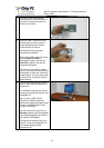
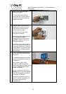
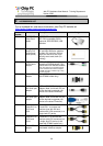
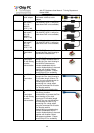
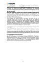
6.3 Non-standard LAN cabling
In some cases cable could be a non standard cable or the far end (patch panel) connected in
a non-standard way (not in accordance to TIA-568-A or B). In such case you will have to do
slightly more work mapping the existing non-standard connections.
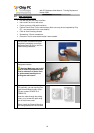
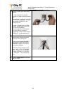
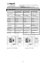
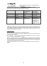
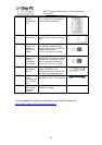
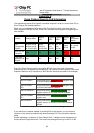
Please refer to the table bellow. This table should be filled at the far end by looking at the
actual connections. Fill out the second column and then use the third column to connect the
wires to the Flex-Jack terminal block according to the numbering shown in the third colum.
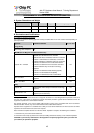
Table 6.1 - Non-standard wiring table
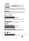
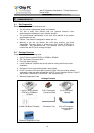
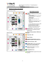
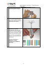
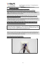
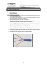
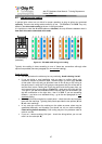
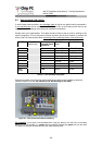
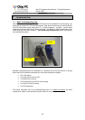
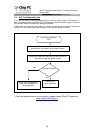
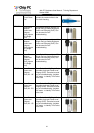
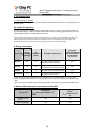
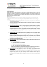
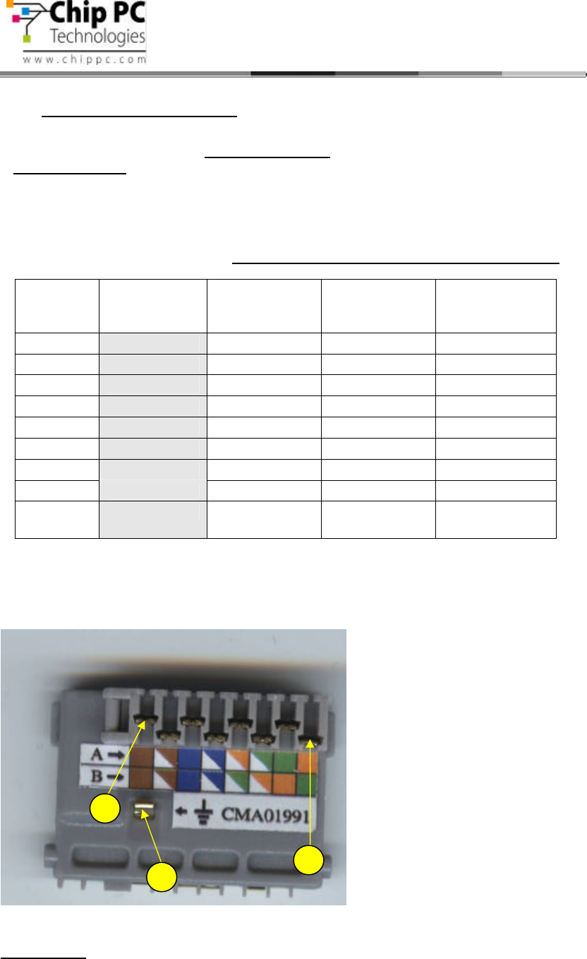
See picture bellow of the Flex-Jack terminal block connections and numbering. Note that
contact numbre 8 is at the left (closest to the A/B marking on the label).
Figure 6.1 - Flex-Jack terminal block numbering
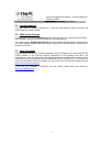
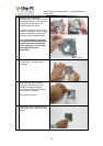
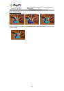
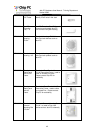
For example, if you have a non-standard wire, and you wrote in the first line of the table
above (RJ-45 Pin number 1) = green, then you need to connect the green wire (on the Jack
PC side) to connector number 3 in the Flex-Jack terminal block.
Tab
RJ-45 Pin Color (Fill
actual color)
Flex-Jack
terminal block
contact #
TIA-568-A
Color
TIA-568-B Color
1
3
White - Green White - Orange
2
2
Green Orange
3
4
White - Orange White - Green
4
6
Blue Blue
5
5
White - Blue White - Blue
6
1
Orange Green
7
7
White - Brown White - Brown
8
8
Brown Brown
Metal
Shield
Tab
Shield Shield