PAGE 4 OF 8 6564XĆX
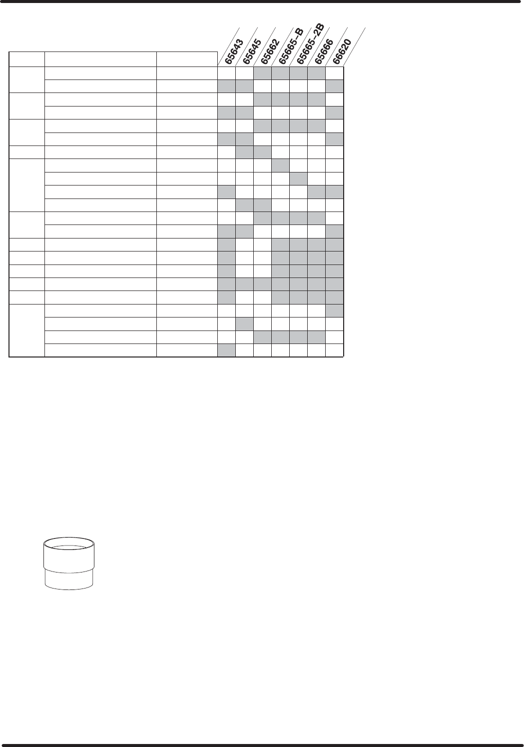
AIR MOTOR PARTS LIST
ITEM DESCRIPTION PART # (QTY)
26 j
Valve Rod 90107Ć1
Valve Rod 90107Ć2
27 j
Air Cylinder 90215Ć1
Air Cylinder 90215Ć2
28 Tube 90485Ć1
Tube 90485Ć2
29 n
O" Ring Y325Ć210
30 Air Motor Base Assembly 65065
Air Motor Base Assembly 65065Ć2
Air Motor Base Assembly 65067
Air Motor Base Assembly L
65868
46 Bolt (1/2" Ć 20 x 10Ć1/4") 94046Ć1 (4)
Bolt (1/2" Ć 20 x 8Ć1/4") 94046Ć2 (4)
47 j
Retaining Ring Y147Ć131
48 j
Guide Washer 73986
49 n
U" Cup Y186Ć16
50 Nut Y11Ć8ĆC (4)
51 j
Washer 90103
52 j
Piston Rod 66628
Piston Rod 90082
Piston Rod 90108Ć1
Piston Rod 90108Ć2
V Smart Parts", Keep these items on hand in addition to the service kits for fast repair and reduction of downtime.
Q See model plate on (30) base for number.
NOTE: Base styles and lower packings may vary from that shown on
the cover. Refer to model number in the chart above.
For simplification of ordering and stocking, a Y325Ć210 O" ring and a
Y186Ć16 U" cup will be included in 61355 service kit. When repairing
the motor, use only the one that is needed.
All of the service parts are the same for all motors except the lower pisĆ
ton rod packing.
L On model 65662 air motors, a plate is mounted on the bottom of the
(30) base. Therefore, the following parts are different and illustrated on
page 8.
93310 Bushing
93311 Retainer
93312 Guide
93313 Plate (note the orientation of the plate with the air inlet)
Y6Ć66ĆC Screw (4 req'd)
Y14Ć616ĆC Lock Washer (4 req'd)
NOTE: It is highly recommended that a 90350 installation tool be used.
This will greatly ease installation of (42) piston adapter and piston
valve and will reduce the chances of damage to the (19) U" cup. A
damaged (19) U" cup can usually lead to air motor failure.
= INDICATES WHERE
PARTS ARE USED.
n PARTS SO MARKED ARE ALSO INĆ
CLUDED IN 61355 SERVICE KIT.
90350 INSTALLATION TOOL
Q AIR MOTOR MODEL NO.
= INDICATES WHERE PARTS ARE USED.
D MODELS NO LONGER ACTIVE, SHOWN
FOR REFERENCE ONLY.
D
D
