25
6.7 BULK-14 DRIVE COUPLER HUB ASSEMBLY REPLACEMENT
Part No. 986893
INSTALLATION INSTRUCTIONS:
1. Remove power.
2. Ensure that unit is at room temperature.
3. Rotate unit to lay on its side.
4. Using a 5/16˝ wrench, remove the four screws from motor and allow motor to fall away from bracket.
Note: DO NOT allow motor to pull on cord.
5. Using a 1/8˝ allen hex key, back out the set screws from both sections of the coupling, pump side and motor side,
and remove the sections.
6. Take the new coupler and slide it onto the pump shaft.
7. Bring the motor back up into position and slide the shaft into the coupler. Hold into position and
reinstall the four screws.
8. Snug up the four screws on the motor, then using your fingers, rotate the coupler on the two (2) shafts. If the
coupler will not rotate, or rotates hard, tap (do not hit) the motor to allow the coupler to rotate. This will ensure
proper alignment of the two (2) shafts.
9. When alignment is complete, tighten the four (4) screws on the motor and align the set screws on the
two (2) shafts to allow the screws to lock on the flats on the shafts. If required, the motor shaft will turn. When
aligned, tighten both set screws.
10. Rotate unit back to its normal position and reconnect power.
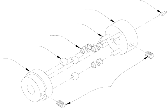
Drive Coupler Pump Side Hub
Dowel Pin
Spring
Coupler Pivot Bearing
Drive Coupler Motor Side Hub
Woodruff Key
Cup Point Socket Set Screw


