22
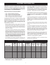
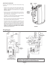
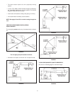
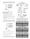
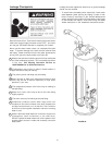
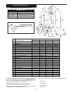
40 AND 50 GALLON 40,000 BTU/HR MODELS
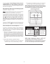
See Chart below for maximum length.
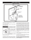
FIGURE 39.
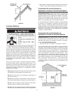
• The total vertical and horizontal vent run cannot exceed the
maximum length with the number of 90
o
elbows as specified
in the following tables. If more are required the venting
distance must be reduced 5 feet for every 90
o
elbow.
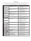
75 GALLON 70,000 AND 75,000 BTU/HR MODELS ONLY
3” DIA. VENT NUMBER OF
MAX. LENGTH (FT.) 90
o
ELBOWS*
70 1
65 2
60 3
55 4
50 5
45 6
75 GALLON 70,000 AND 75,000 BTU/HR MODELS ONLY -
OPTIONAL 4” VENT PIPING
4” DIA. VENT NUMBER OF
MAX. LENGTH (FT.) 90
o
ELBOWS*
110 1
105 2
100 3
95 4
90 5
85 6
ALL 40 AND 50 GALLON 40,000 BTH/HR MODELS ONLY
3” DIA. VENT NUMBER OF
MAX. LENGTH (FT.) 90
o
ELBOWS*
115 1
110 2
105 3
100 4
95 5
90 6
ALL 40 AND 50 GALLON 40,000 BTH/HR MODELS ONLY -
OPTIONAL 2” VENT PIPING
2” DIA. VENT NUMBER OF
MAX. LENGTH (FT.) 90
o
ELBOWS*
50 1
45 2
40 3
35 4
30 5
25 6
* Two 45
o
elbows are equivalent to one 90
o
elbow.
One 90
o
elbow equals 5 feet of equivalent vent length.
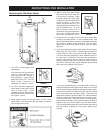
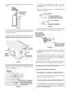
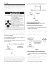
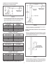
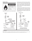
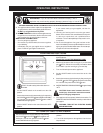
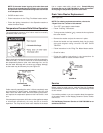
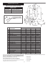
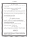
FIGURE 40.
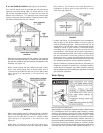
• Minimum vent length for all 40,000 BTU/HR input models is
4 feet and 16 inches for all other models.
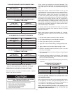
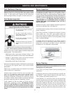
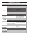
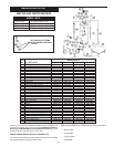
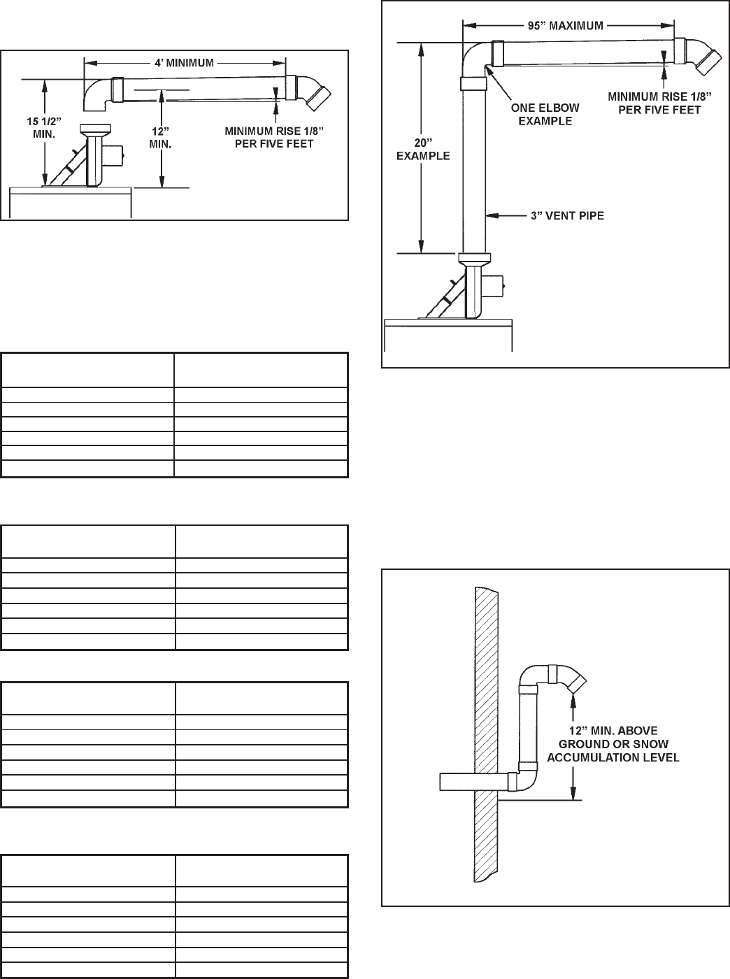
VENTING THROUGH AN OUTSIDE WALL WITH LOW GROUND
CLEARANCE
• When the venting piping cannot pass through an outside
wall at a height greater than or equal to 12” above the ground
(or above snow accumulation level), then the installation
can be modified as shown below.
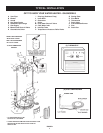
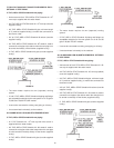
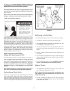
FIGURE 41.
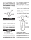
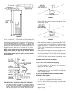
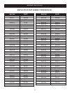
• Refer to the tables on page 23 for maximum vent lengths for
low ground clearance installations. All installations assume
the use of two additional 90 elbows and the standard 45
o
vent cap with screen outside of the exterior wall.