2
Installation Manual P/N 01 29 0 393 657
Procedure:
1. Disconnect negative battery terminal.
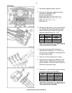
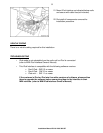
2. Remove the following components using
information available in TIS:
• Drivers knee bolster (1)
• Center dash face (3)
(Refer to RA62 21 001)
• Radio side pillars (4)
(Refer to RA51 16 198)
• Radio (5)
(Refer to RA 65 11 030)
• Glove box (6)
3. Remove the blue lock (1) from radio harness
by releasing tab and sliding upwards, then
remove following terminals (2) using AMP
terminal removal tool p/n 61 1 134:
Pin # Color Description
9 White/Red I-Bus
12 Brown Ground
15 Red/Brown KL 30
16 Violet/Blue KL-R
Note: Wire colors may vary depending on
vehicle production changes.
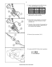
4. Cut original terminals off of 4 wires (1)
removed from locations 9, 12, 15 &16. Cut
wire as close as possible to existing terminal
to maintain wire length.
5. Strip 1/8” of wire shielding from 4 wires.
6. Using terminal crimping tool (BMW p/n 408
449 or Snap-on PWC47) crimp new female
bullet connectors included in kit onto each of
the wires from previous step.
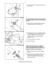
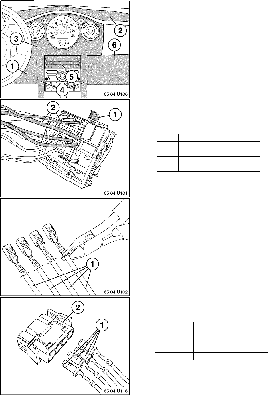
7. Insert pins (1) removed from radio connector
into 4-pin connector (2) as follows:
Note: Wire colors may vary depending on
vehicle production changes.
Color Location Description
Violet/blue 1 KL-R
Red/brown 2 KL 30
White/red 3 I-Bus
Brown 4 Ground