PAGE 52 — DCA-180SSJU — OPERATION AND PARTS MANUAL — REV. #3 (02/01/10)
Starting (Manual)
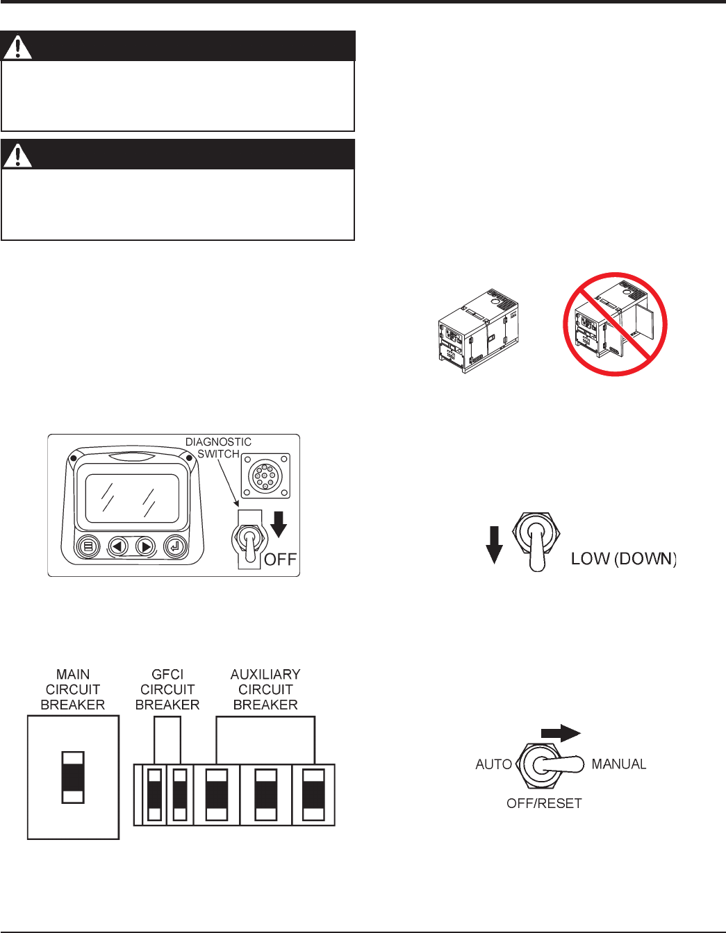
1. Place the engine speed switch (Figure 42) in the
“
LOW
” (down) position
Figure 43. MPEC Control Switch
(Manual Position)
GENERATOR START-UP PROCEDURE (MANUAL)
The engine's exhaust contains harmful emissions.
.
Direct exhaust away from nearby personnel.
Before Starting
Figure 41. Engine Enclosure Doors
2. Place the and circuit breakers
(Figure 40) in the OFF position prior to starting the
engine.
Figure 40. Main, Aux. and GFCI
Circuit Breakers (OFF)
3. Make sure the the
voltage change-over board
has
been configured for the desired output voltage.
4. Connect the load to the or the
as shown in Figure 14. These load
connection points can be found on the output terminal
panel and the output terminal panel’s hard wire hookup
panel.
5. The output terminal lugs are protected by a plastic cover.
Remove this cover to gain access to the terminals. Tighten
terminal nuts securely to prevent load wires from slipping
out.
6. Close all engine enclosure doors (Figure 41).
CAUTION - LETHAL EXHAUST HAZARD
2. Place the in the MANUAL
position to start the engine (Figure 43). Observe that the
Warning and Emergency Stop lamps on the Engine
Operating Panel are lit during the initial starting of the
engine. If no abnormal conditions exists, both lamps will
turn off.
Figure 42. Engine Speed Switch (Low)
manually start the engine with the , or
circuit breakers in the ON (closed) position.
WARNING - STARTING THE GENERATOR
The Engine Control Unit (ECU) used with this generator
diagnosis engine faults that arise with the the engine control
system and the engine itself. Engine faults can be determined
by viewing the Diagnostic Trouble Codes (Active Fault Codes)
which are displayed on the Diagnostic Display Panel located
inside the Control Box.
1. Before starting the engine, make sure the diagnostic
switch (Figure 39) on the Diagnostic Display Panel
Assembly is in the “OFF” position.
Figure 39. Diagnostic Switch (OFF poistion)
INCORRECTCORRECT


