Index
© National Instruments Corporation I-3 PXI-1006 User Manual
R
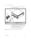
rack mounting, 2-6
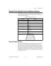
remote power monitoring and inhibiting
interface, 2-7
S
safety ground, connecting, xi
safety specifications (table), A-3
safety, warning and caution notices, xi
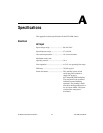
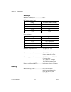
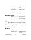
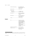
specifications, A-1
backplane, A-4
cooling, A-2
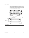
dimensions (figure), A-6
electrical, A-1
electromagnetic compatibility, A-3
environmental, A-3
mechanical, A-5
safety, A-3
StarTrigger(ST)slot
description, 2-4
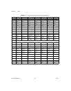
P1 (J1) connector pinouts (table), B-4
P2 (J2) connector pinouts (table), B-5
system controller slot
description, 2-4
P1 (J1) connector pinouts (table), B-2
P2 (J2) connector pinouts (table), B-3
system integration, by National Instruments,
C-1
system reference clock, 2-6
T
technical support resources, C-1
trigger bus, 2-6
troubleshooting the PXI-1006 (table), 3-1
V
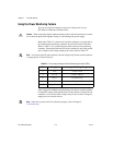
voltages at power monitoring connector
(DB-9) (table), 2-8
W
Web support from National Instruments, C-1
worldwide technical support, C-2