SERVICE AND ADJUSTMENTS
TO LEVEL MOWER HOUSING °
Adjust the mower while tractor is parked on level ground or
driveway. Make suretiresare propedy inflated (See"PROD-
UCT SPECIFICATIONS" sectionofthis manual). Iftiresare
over or underinflated, you will not properly adjust your
mower.
SIDE-TO-SIDE ADJUSTMENT (See Figs. 16 and 17)
• Raise mower to itshighest position.
• At the midpoint of bothsides of mower, measure height
from bottom edge of mower to ground. Distance"A'on
both sides of mower should he the same or within 1/4"
of each other.
• If adjustment is necessary, make adjustment on one
side of mower only.
• To raise one side of mower, tighten llft link adjustment
nut on that side.
• To lower one side of mower, loosen lift linkadjustment
nut on that side.
NOTE: Three full turnsofadjustment nutwillchange mower
height about 1/8".
• Recheck meesurements afteradjusting.
BOTTOM EDGE BOI'rOM EDGE
OF OF MOWER
MOWER
TO GR_OUN D
_GROUND UNE-"''-
FIG. 16
oo_SUSPENSION ARM
/
" IIJ:_i\\ MR" UNK
.-ADJUSTMENT
NUT
FIG. 17
FRONT-TO-BACK ADJUSTMENT (See Figs. 18 and 19)
IMPORTANT: DECK MUST BE LEVEL SIDE-TO-SIDE. IF
THE FOLLOWING FRONT-TO-BACK ADJUSTMENT IS
NECESSARY, BE SURE TO ADJUST BOTH FRONT LINKS
EQUALLY SO MOWER WILL STAY LEVEL SIDE-TO-
SIDE.
To obtain the best cuttingresults,the mower housingshould
be adjusted so that the front is approximately 1/8" to 1/2"
lower than the rear when the mower isin itshighest position.
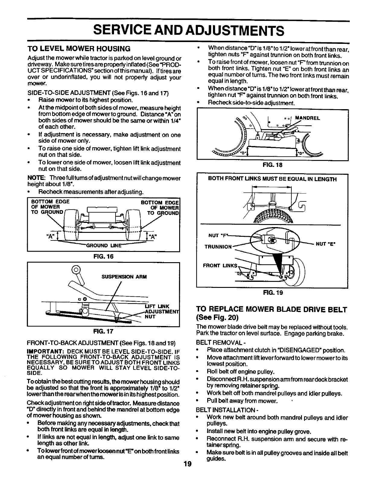
Check adjustment on rightsideof tractor. Measure distance
=13"directly infront and behind the mandrel at bottom edge
of mower housing as shown.
• Before making any necessary adjustments, checkthat
both front links are equal in length.
• If links are not equal in length, adjust one link to same
length as other link.
• Tolower front nt mowerlooeen nut"E" on bothfront links
an equal number ofturns.
19
When distance =D"is 1/8"to 1/2" lower at front than rear,
tighten nuts "F* against trunnion on both front links.
To raisefront of mower,loosen nut"F" from trunnionon
both front links. Tighten nut "E"on both front links an
equal numborofturns. The two front linksmustremain
equal inlength.
When distance=D"is1/8"to 1/2"lower at front than rear,
tighten nut"F-"against trunnion on both front links.
Recheck side-to-side adjustment.
MANDREL
FiG. 18
BOTH FRONT LINKS MUST BE EQUAL IN LENGTH
FRONT I..IN___
RG, 19
TO REPLACE MOWER BLADE DRIVE BELT
(See Fig. 20)
The mower blade drive belt may be replaced without tools.
Park the tractor on level surface. Engage parking brake.
BELT REMOVAL -
• Place attachment clutch in =DISENGAGED" position.
• Move attachment liftleverforward to lower mower to its
lowest position.
• Roll belt off engine pulley.
• DisconnectR.H. suspensionarm from reardeck bracket
by removing retainer spring.
• Work bolt off both mandrel pulleys and idler pulleys.
• Pull belt away from mower.
BELT INSTALLATION -
• Work new belt around both mandrel pulleys and idler
pulleys.
• Install new belt into engine pulley grove.
• Reconnect R.H. suspension arm and secure with re-
tainerspring.
• Make sure belt isin allpulley groovesand inside all belt
guides.


