©Titan Tool Inc. All rights reserved. 23
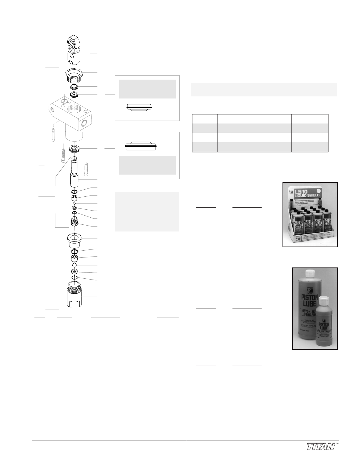
Fluid Section Assembly
Item Part # Description Quantity
1 704-120 Fluid section complete..........................1
1A 704-085 Fluid section complete (includes filter
and PRIME/SPRAY valve assembly)
2 704-090 Piston assembly (includes items 8–14).....1
3 700-735 Connecting rod. ....................................1
4 730-508 Retainer ................................................1
5 700-587 Piston guide..........................................1
6 700-603 Upper packing ......................................1
7 700-601 Lower packing .....................................1
8 704-089 Piston rod .............................................1
9 762-111 Upper seal ............................................1
10 762-135 Upper cage ...........................................1
11 762-144 Outlet valve ball....................................1
12 762-134 Outlet valve seat...................................1
13 762-057 O-ring....................................................1
14 762-073 Outlet vavle retainer .............................1
15 730-509 Bushing.................................................1
16 700-821 Lower seal ............................................1
17 730-510 Lower cage ...........................................1
18 762-145 Foot valve ball ......................................1
19 762-137 Foot valve seat .....................................1
20 762-058 O-ring....................................................1
21 704-054 Foot valve housing ...............................1
22 762-202 Packing tool (not shown) ......................1
1
2
3
4
5*
6*
7*
8
9*
13*
14
10
16*
17
19
20*
12
11*
15
21
18*
Install lower packings
with raised lip and O-ring
facing up.
Install upper packings
with raised lip and O-ring
facing down.
O-Ring
O-Ring
Raised Lip
Raised Lip
NOTE: Packing kit P/N
704-113 includes those
items marked with an *.
Also included are packing
grease P/N 700-203 and
piston guide tool
P/N 700-793.
Accessories
Airless Tip Selection
Tips are selected by the orifice size and fan width. The proper
selection is determined by the fan width required for a specific
job and by the orifice size that will supply the desired amount
of fluid and accomplish proper atomization.
For light viscosity fluids, smaller orifice tips generally are
desired. For heavier viscosity materials, larger orifice tips are
preferred. Please refer to the chart below.
The following chart indicates the most common sizes and the
appropriate materials to be sprayed.
Fan widths measuring 8" to 12" (20 to 30 cm) are most
preferred because they offer more control while spraying and
are less likely to plug.
Liquid Shield
Cleans and protects spray systems
against rust, corrosion and premature
wear.
Part No.
Description
700-888...........Case of 12
(1 quart bottles)
700-889...........1 Quart
Piston Seal Lubricant (P.S.L.)
Specially formulated to prevent materials
from adhering to the piston rod, which
becomes abrasive to the upper seals.
Piston Lube will break down any material
that may accumulate in the wet cup and
keep it from drying.
Part No.
Description
700-925...........8 Ounce Individual
700-926...........1 Quart Individual
700-911 ...........Case of 12
(8 ounce bottles)
700-912...........Case of 12
(1 quart bottles)
Miscellaneous
Part No. Description
490-012...........Hose Coupling, 1/4" x 1/4"
730-397...........High Pressure Fl. Gauge
Tip Size Spray Material Filter Type
.011 — .013 Laquers and stains 100 mesh filter
.015 — .019 Oil and latex 50 mesh filter
.021 — .026 Heavy bodied latex and blockfillers 5 mesh filter
NOTE: Do not exceed the pump's recommended tip
size.


