14 © Titan Tool Inc. All rights reserved.
12. Line up the three holes in the taper lock bushing with the
three holes in the clutch hub and insert the bushing into
the center of the clutch hub.
13. Line up the key on the taper lock bushing with the keyway
on the engine shaft and slide the assembly onto the shaft
with the holes facing out.
Clutch
Housing
0.20"
Engine
Set
Screw
Straight
Edge
Taper
Lock
Bushing
14. Apply blue Loctite to the
two set screws and insert
the screws into the taper
lock bushing. Tighten the
set screws only two turns
at this time.
15. Line up the forward face
of the clutch hub with the
front face of the clutch
housing. Using an 1/8”
hex wrench, alternately
tighten the set screws
into the taper lock
bushing. Torque to 65–75 in/lbs.
NOTE: To ensure the clutch hub and the clutch housing are
aligned, hold a straight edge across the face of the
clutch housing and then hold the clutch hub against
the back of the straight edge while tightening the
two set screws into the taper lock bushing.
16. Make sure the friction surface of the clutch armature is
clean and free from oil or grease.
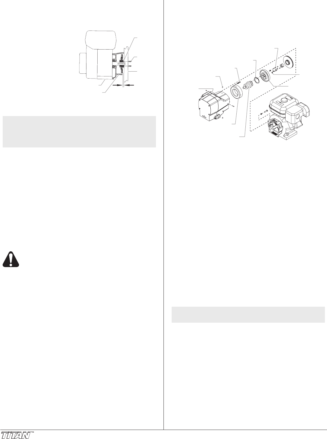
Removing the Clutch Rotor, Clutch Field, and Drive
Shaft Assembly
1. Follow steps 1–7 in “Removing/Replacing the Clutch Hub
and Armature Assembly.”
2. Locate the clutch rotor assembly on the end of the drive shaft
assembly. Note the locations of the three socket screws and
the two empty, threaded holes on the clutch rotor.
3. Using a 3/16” hex wrench, remove the three socket
screws and lock washers that secure the clutch rotor to
the drive shaft assembly.
4. Thread two of the socket screws into the empty, threaded
holes and tighten alternately. This will push the clutch
rotor away from the drive shaft assembly and pinion.
Electrostatic discharge (ESD) potential could cause
damage to electronic pressure control. Use Titan
ESD wrist strap P/N 700-1037 or equivalent when
working on electronic pressure control.
5. Using a Phillips screwdriver, remove the four screws that
secure the EPC assembly to the EPC housing. Carefully
remove the EPC assembly from the housing.
6. Locate the two clutch eld wires that pass from the gear
housing into the EPC housing through a grommet in the
back of the EPC housing. Remember the wire connection
terminals on the EPC assembly (label if necessary) and
disconnect the wires. Gently move the EPC assembly
away from the housing and rest it on the work surface by
the control housing.
7. Locate the four set screws that secure the clutch eld to
the gear housing. They are located on the exterior of the
gear housing at the 12, 3, 6, and 9 o’clock positions while
facing the clutch eld end of the gear housing. Using an
1/8” hex wrench, remove the setscrews. Remember the
location of the two clutch eld wires with respect to the
grommet and EPC housing.
8. Carefully slide the clutch eld out of the gear housing,
keeping the eld square to the gear housing so it does not
bind.
9. Remove the retaining ring in front of the ball bearing within
the center bore of the gear housing.
10. Follow steps 2–6 in the “Replacing the Gears” procedure
to remove the pump housing from the gear housing.
11. From the gear side of the gear housing, use a soft
hammer to tap the gear end of the drive shaft through the
gear housing.
12. Carefully slide the drive shaft assembly out from the gear
housing, keeping the shaft square to the housing so it
does not bind.
13. Remove the o-ring from inside the center bore of the gear
housing from which the small ball bearing on the drive
shaft assembly was removed.
14. Clean the inside of the gear housing.
Clutch Rotor
Socket Screw
Retaining Ring
Clutch Field Wires
Drive Shaft
Assembly
Clutch
Field
Clutch Field
Set Screw
EPC
Housing
Lock
Washer
Clutch
Rotor
Installing the Clutch Rotor Assembly, Clutch Field and
Drive Shaft Assembly
1. Install a new o-ring into the center bore of the gear
housing.
2. Apply Loctite retaining compound #635 to the outside
diameter of the large bearing on the drive shaft. Do not
get retaining compound on the faces of the bearing.
3. Install the drive shaft assembly into the center bore of the
gear housing, keeping it square to the housing so it does
not bind. Once the large ball bearing on the drive shaft
assembly is half way into its bore, a soft hammer may be
used to gently tap the assembly into position.
IMPORTANT: Do not force the drive shaft assembly into
position.
4. Install the retaining ring into its groove next to the large
ball bearing.
5. Line up the four holes around the outside of the clutch eld
with the four set screw holes in the gear housing. The
clutch eld wires should be at approximately the 1 or 2
o’clock position.
6. Route the two clutch eld wires through the grommet and
into the EPC housing.
7. Carefully slide the clutch eld into its bore in the gear
housing until it “bottoms out” within the housing. Do not
pinch the clutch eld wires during installation.
NOTE: Apply blue Loctite to the four clutch eld set
screws prior to installation.
8. Thread one of the set screws into its hole. Using an 1/8”
hex wrench, rotate the screw slowly until it contacts the
clutch eld. Do not tighten the set screw. The tip of the
set screw should mate with the drill point hole in the eld.
Check the clutch eld for rotation. If it rotates within its
bore, the set screw is not seated within the drill point.
9. When the set screw is properly seated, install the
remaining three set screws. Do not tighten the set screws.
10. Using a crossing pattern, tighten each of the setscrews
until they are snug. Once all four set screws are snug,
use a crossing pattern to tighten and torque the set screws
to 30–40 in./lbs.
IMPORTANT: It is very important to evenly snug, tighten,
and torque the clutch field set screws in a crossing pattern.
This ensures the clutch field will stay centered in the gear
housing.


