


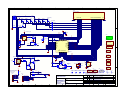
both halves of the following stage receive an equal AC signal
component at high frequency.
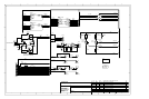
TR310 and TR307 are the ‘pre-driver’ transistors, which act to
buffer the outputs from the preceding stage and drive the
Darlington output power transistors. TR309 and R321 act as a
current limit, to ensure that the emitter current of TR310 does not
exceed 30mA in a fault condition. TR306 and R323 provide the
same function for TR307.
R338 and R339 are to loosely couple the outputs of the pre-driver
stage to the inputs of the Darlington power output devices. This is
so that the inbuilt temperature sensing diodes of the output
transistors can accurately control the quiescent current of the
output stage as the junction temperature of the power devices
varies. C312 and C318 ensure that both halves of the output stage
receive an equal AC signal component.
The output transistors are TR318 and TR319. These are Sanken
SAP15N and SAP15P devices respectively. They are specially
designed for audio power amplifier use. In addition to high current
gain (Darlington with a typical h
FE
of 20,000) they provide an
inbuilt emitter resistor (thick film power resistor of 0W22) and
temperature sensing diodes which closely and rapidly track the
V
BE
versus temperature characteristic of the power transistors,
allowing for easy, fast-responding and reasonably accurate control
of quiescent current (one of the major headaches of class B
amplifier design!)
RV300 is for fine trimming of the quiescent current. PL300
provides a convenient measuring point for this, which is short-
circuit protected in the event of a slip with the multimeter probe!
All of the remaining circuitry to the right of TR318 and TR319 is
essentially for output stage protection...
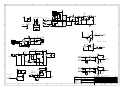
Transistors TR312 and TR304, along with the network of resistors
and capacitors to which they are connected, provide instantaneous
overload protection of the output stage. This is a conventional
single slope VI protection scheme, which allows much greater
current to be delivered into a rated load than into a short circuit.
The values allow for 18A peak delivery (at clip) into a purely
resistive load, 7A peak (at clip) into a purely capacitive load and
around 4A peak into a short circuit. R345, C303, R346 and C304
allow these values to be doubled for short transient bursts
(approximately 2.7 milliseconds) so that impulsive musical
transients can be delivered cleanly with minimal risk of damaging
the output transistors.
TR313, TR302 and their associated components send a signal to
the microprocessor when the instantaneous protection circuits are
having to work ‘hard’ to prevent amplifier overload. This instructs
the micro that the user is severely abusing the amplifier and will
switch off the loudspeaker relays to prevent possible permanent
damage. In reality, if you short circuit the outputs at any
appreciable volume level, this circuit will trigger and the
microprocessor will turn off the loudspeaker relays and send a
signal to the user.
R308, R314 and C320 form a low pass filter from which the DC
detection circuits can sense excessive DC at the loudspeaker
outputs. If there is any positive DC present, then TR316 will turn
on, which turns on TR305 and thus activates the DC protection
line to the micro, turning off the loudspeaker relays.
If there is any negative DC present, then TR308 will turn on,
which turns on TR317 which then turns on TR305 in turn, causing
the same effect.
R350 and C319 are the Zobel network which is provided to ensure
the amplifier ‘sees’ a constant and resistive load at very high
frequencies, to aid stability, although the amplifier will be stable
without the Zobel fitted.
C313 locally couples the ‘high frequency’ and loudspeaker ground
returns together at the output to overcome the effects of track
inductance back to the star point. C309 couples the ‘high
frequency’ and signal grounds together at the input for the same
reason.
D303 and D304 are ‘flyback’ diodes to protect the output
transistors from reverse bias when the amplifier is heavily clipped
into an inductive load (such as a loudspeaker voice coil!)
Sheet 4 is an identical copy of sheet 3 so I will not describe it
separately.
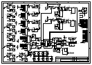
L870 Phono Circuit Description
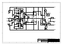
The Phono board is a simple single stage RIAA amplifier. It
consists of two channels of high gain amplification, and switching
between moving magnet (MM) and moving coil (MC) settings.
PSU
The unit derives its ±15V regulated rails from the unit it is fitted
into with only local decoupling capacitors on board.
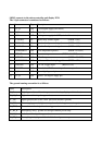
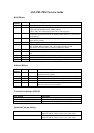
Interface
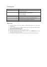
The unit connects to the host unit via a 8 way connector:
Amplifier
The left channel has designators beginning with 100, and the right
with 200. For the purposes of this description the left channel will
be described, as the right channel the same in all respects.
The amplifier is a small signal class A voltage feedback amplifier
with switchable gain. The input consists of an actively loaded
differential pair of very low noise PNP transistors (TR106,107).
These transistors are very specific and should only be replaced
with identical parts with the E grade high gain. TR100 & TR101
form a current source for the pair, which sets the quiescent current
for the entire amplifier. The active load consists of TR110 &
TR111, which forms part of a differential current mirror with
TR112,113 & 114. This differential stage also has an active load
(TR102 & TR103) to keep gain to a maximum.
Both of these differential stages are designed to have as much gain
as possible to enable the single stage design. The RIAA response
is achieved in the feedback network:
C101,110,111,112,119,120,&R115,112. C115 is used to correct
between MM & MC gains as the amplifier is non-inverting.
SW100 switches between MM & MC. Two poles of the switch
change between the different loading required for each type of
cartridge: R108 & C109 for MM, and added in parallel for MC
R104 & C108. The other two poles change the feedback resistor
value to alter the gain. MM: R105 and in parallel for MC R123.
The DC offset is controlled by a non-inverting servo built around
IC100. The amount of servo current is different for each gain
setting via R111 (MM) & R124(MC) so that the low frequency
high pass point remains the same for both settings. However the
high pass point for the circuit is set by C113. This gives a warp
filter, stops DC startup thumps from upsetting DC coupled
circuitry and an approximation of the RIAA/IEC curve (-2dB @
20Hz).
The output is class A buffered by a dual mirror follower
(TR104,105,108,109). The quiescent current is set up by D100
and R118,119.
Closed loop stability is achieved with C116,117, giving
symmetrical slewing capability.