


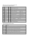
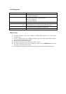

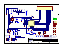

SK103 connects to the micro controller and display PCB.
The 14 pin connector is numbered as follows:
No Name Type Description
1 +5V_D O/P 5 volt digital supply (for micro)
2 0V_D O/P Digital ground
3 +49V O/P Main power supply for VFD (via fusible resistor)
4 STANDBY I/P Mains relay control signal (HIGH = ON)
5 SPKR1 ON I/P Speaker 1 relay control signal (HIGH = ON)
6 SPKR2 ON I/P Speaker 2 relay control signal (HIGH = ON)
7 THERMPROT O/P Over temperature protect (HIGH = FAULT)
8 VIPROT O/P Short circuit protect (HIGH = FAULT)
9 DCPROT O/P DC offset protect (HIGH = FAULT)
10 AC PRESENT O/P Indicates AC mains is plugged in (HIGH = ON)
11 TRIGGER O/P 12V DC trigger input (HIGH = ON)
12 REMOTE O/P Demodulated RC5 remote input from rear panel
13 0V_D O/P Spare digital ground pin
14 +5V_D O/P Spare 5 volt digital supply pin
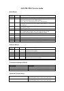
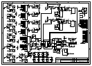
The ground naming convention is as follows:
Name Description
0V_D Digital ground (used for micro processor circuitry, display and interface)
0V_LS_R Right channel loudspeaker ground return
0V_SIG Signal ground (this is the ‘clean’ precision reference ground)
0V_PSU Power supply ground (high current pulses for the large reservoir caps)
0V_TRIG Ground return for the jack socket trigger and remote control circuit
0V_HF_R Decoupling ‘noisy’ ground for the right channel power amp
0V_LS_L Left channel loudspeaker ground return
0V_HF_L Decoupling ‘noisy’ ground for the left channel power amp