


31-EN
01GB05CDE101E.fm
ALPINE CDE-101E 68-09359Z76-B (EN)
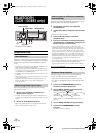
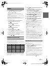
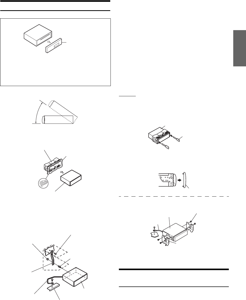
Installation
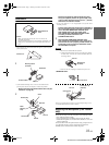
• The main unit must be mounted within 35 degrees of the horizontal
plane, back to front.
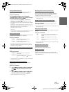
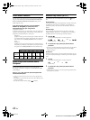
Removal
1. Remove the detachable front panel.
2. Insert the bracket keys into the unit, along the guides
on either side. The unit can now be removed from the
mounting sleeve.
3. Pull the unit out, keeping it unlocked as you do so.
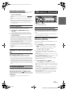
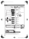
<JAPANESE CAR>
Secure the ground lead of the unit to a clean metal spot using a screw
(*
3
) already attached to the vehicle’s chassis.
Mounting the Microphone (CDE-103EBT
only)
For the sake of safety, mount the microphone in the following location.
• In a stable and secure location.
• In a location that does not inhibit safely driving the vehicle.
• Mount the microphone in a location where the driver’s voice can
easily be picked up.
Choose a location for the microphone that can easily pick up the driver’s
voice. Requiring the driver to move towards the microphone for
audibility causes a distraction that could be dangerous.
Caution
When you install this unit in your car, do not remove the
detachable front panel.
If the detachable front panel is removed during installation, you
might press too hard and warp the metal plate that holds it in
place.
1
* If the installed mounting sleeve is loose in the dashboard, the
pressure plates may be bent slightly to remedy the problem.
Remove the mounting sleeve from the main unit (see
“Removal” on page 31).
2
Detachable Front
Panel
Less than 35°
Mounting Sleeve
(Included)
Dashboard
This unit
Pressure Plates
*
Metal
Mounting
Strap
Chassis
Hex Nut (M5)
Bolt Stud
Ground Lead
Screw
This unit
*
2
*
1
Reinforce the head unit with the metal mounting
strap (not supplied). Secure the ground lead of the
unit to a clean metal spot using a screw (
*
1
) already
attached to the vehicle’s chassis.
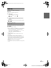
• For the screw marked “*
2
”, use an appropriate screw for the chosen
mounting location.
Connect each input lead coming from an amplifier to
the corresponding output lead coming from the left
rear of the CDE-103EBT/CDE-102E/CDE-101E/
CDE-101EM. Connect all other leads of the
CDE-103EBT/CDE-102E/CDE-101E/CDE-101EM
according to details described in the
CONNECTlONS section.
3
Slide the CDE-103EBT/CDE-102E/CDE-101E/
CDE-101EM into the dashboard until it clicks. This
ensures that the unit is properly locked and will not
accidentally come out from the dashboard. Install
the detachable front panel.
Bracket Keys
(Included)
This unit
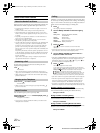
Front Frame
This unit
Screws (M5 × 8)
(Included)
Mounting Bracket
Ground Lead
*
3
01GB00CDE101E.book Page 31 Monday, November 3, 2008 10:12 AM