


9
12345
678910
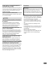
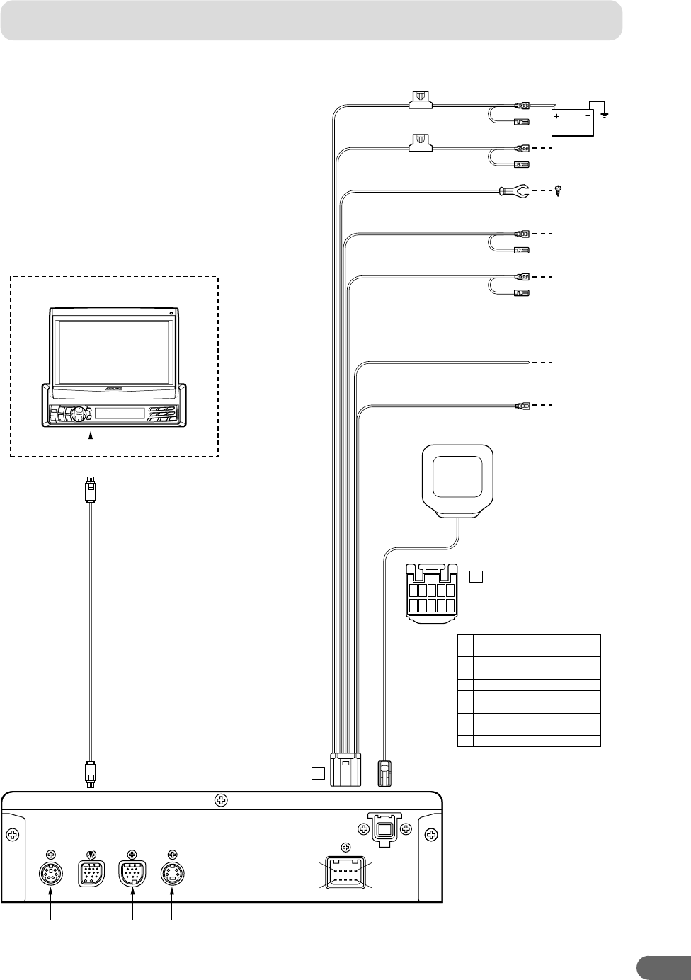
Battery Lead (Yellow)
(5A)
(5A)
Ignition (Red)
BATTERY
GPS Antenna (Included)
Ground (Black)1
CVA-1003
Ground (Black)
Illumination (Dimmer) (+) (White/Blue)
Parking Brake (Yellow/Blue)
13P RGB Extension Cable Included
Speed Sensor (Green/White)
Connect to VSS (Digital or Analog 0V – 3V)
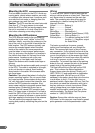
A
A
1
6
5
10
Acc (Ignition) (Red)2
Mute (Pink/Sky blue)3
Open4
Open5
Battery (Yellow)6
Dimmer In (Illumination) (White/Blue)7
Speed Sensor (Green/White)8
Parking Brake (Yellow/Blue)9
Open10
Mute (Pink/Sky blue)
POWER
EX-2EX-1TO DISP.MIC/SW
GPS ANT.
To the Acc power lead
To the Illumination
signal line
To the parking brake
signal line
Connect to a metal
part of chassis
body with screw
*
To the vehicle speed
pulse line
Use this to connect
a device having the
IN-INT function
Use this to connect
a device having the
IN-INT function (–)
output for Audio Mute
Use for future system expansion
3.
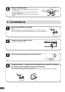
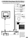
NVE-N852A Wiring Diagram With CVA-1003 etc.
Power Connector Pin
Configuration
* Improper connection of the
speed pulse line may cause
important safety features of
the vehicle to fail (such as
the brakes or air bag). Such
failures may result in an
accident and loss of life. We
strongly recommend that the
installation be performed by
a trained, authorized Alpine
dealer.
Note: SOLDER ALL
CONNECTIONS
∗ The connecting with CVA-1005/CVA-1006/IVA-C800/IVA-C801/TME-M750/
TME-M750A/TME-M790 are also the same as this diagram.