


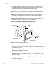

Installation
10
Color Passive-Matrix LCD Touch Panels
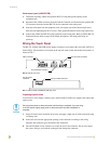
Using the (DB-9) RS-232 connector for mouse control or data
The dual-function (DB-9) RS-232 connector supports most standard serial mouse control devices
and RS-232 communication protocols for PC data transmission. Refer to the TPDesign or
TPDesign3 Touch Panel Program instruction manual for data transmission information.
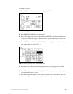
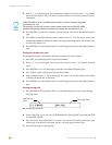
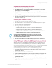
The table below lists (DB-9) RS-232 connector pinouts and FIG. 10 shows the (DB-9) RS-232
connector and power supply wiring diagram.
Use connector pins 2, 3, and 5 for data and ground. For some applications, you may need to strap
pins 7 (request to send) and 8 (clear to send) together depending on the PC.
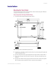
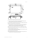
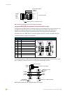
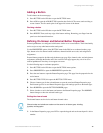
FIG. 9 AXlink and external 12 VDC power supply wiring diagram
(DB-9) RS-232 Connector Pinouts
Pin Signal Function
1 N/A Not used
2 RXD Receive data
3 TXD Transmit data
4 DTR Data terminal ready (not used)
5 GND Signal ground
6 DSR Data set ready (not used)
7 RTS Request to send (not used)
8 CTS Clear to send (not used)
9 N/A Not used
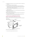
FIG. 10 DB-9 RS-232 connector and power supply wiring diagram
PWR (+)
AXP
AXM
GND (-)
PWR (+)
AXP
AXM
GND (-)
AXlink connector on the touch panel
Central Controller
PWR (+)
GND (-)
12 VDC power supply
9
8
7
6
5
4
3
2
1
9
8
7
6
Female
Male
DB-9 (male)
DB-9 (female)
Power connector
Mouse or PC, DB-9 connector
Female
Male
Touch panel
DB-9 connector
Optional 7 to 8-pin
connector
2 (RXD)
3 (TXD)
5 (GND)
2 (RXD)
3 (TXD)
5 (GND)
+ (PWR)
- (GND)
12 VDC power supply