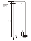
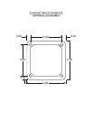
5. Use the template provided on page 10 for proper placement of the junction box
mounting holes. Use the #8 self-drilling screws (included) to secure the junction
box in the desired location. The junction box can also be mounted using the 2”x 4”
velcro strip (included).
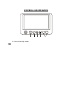
6. There are 2 options for connecting the LCD monitor to the junction box. If the
application is such that the monitor is in close proximity to the junction box, the
AOM703 monitor can be connected directly to the junction box. If the junction box
is mounted further from the monitor, use the 5’ intermediate cable included with the
AOM703 to connect the monitor to the junction box. If more cable length is needed,
additional 5’ lengths of the intermediate cable can be purchased. (See the accessory
list at the back of this manual for part number details.)
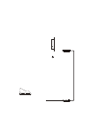
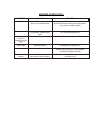
7. Connect the 6-pin power harness to vehicle. (See system connection illustration
page 8)
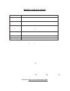
8. Plug camera extension cable (available separately) into AV1, AV2 or AV3 input
connector on the junction box. Plug observation camera into camera
extension cable.
9. Make sure all cables are routed away from hot or moving parts, and away from
sharp edges. Secure cables with wire ties.
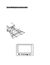
10. For rear observation applications, range marker stickers have been included with
this product. These markers are designed to adhere to your LCD monitor and
provide a reference for gauging distance. See page 9 for illustration showing
proper use and installation of the range markers
7


