


4
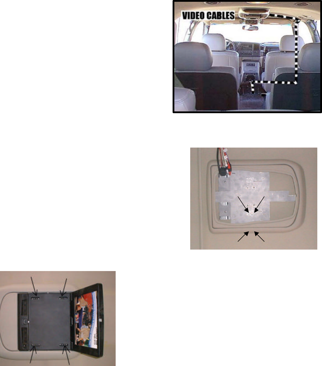
6. Install and route all video and audio cables, and any other
added component requirements to their respective places in
the vehicle. Refer to component installation instructions for
wiring diagrams. The suggested routing of the video system
cable is as follows: Above the headliner from video system
to the B-pillar. Down the B-pillar to the floor. Route the
power lead to a fused accessory controlled source. Connect
the ground lead to the vehicle chassis. Route the remaining
wiring (RCA plugs, Remote Sensor extension, etc.) to the
VCP location. See Figure 4. Connect per instructions
included with the video system. If video system if to be used
as a television, install an appropriate antenna per instructions
included with the antenna.
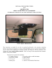
INSTALLATION OF CONSOLE
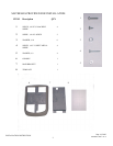
7. Raise console (item 6 pg 2) into position against the headliner.
Install 4 screws (item 1 pg 2) and 4 washers (item 3 pg 2) to
secure console into place.
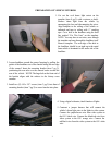
8. Install appropriate plastic insert into recess in the main console.
Release video screen from locked position. Lower video screen to
viewing position for access to mounting locations in top of video
system housing.
9. Raise video system into approximate position and connect all wiring
to components. Connect wiring and cabling to video system per
instructions included with video system.
10.Check function of all components and lights. See operating
instructions for video system operations check. For further assistance,
refer to the video system manual for the technical support phone
number listed for your area.
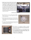
11.Insert video system into opening in console. Note: Make sure wires
do not get pinched between video system and console. Align
holes in housing with holes in mounting bracket. Secure using 4 screws
(item 4 pg 2) and 4 washers (item 5 pg2).
Caution: Do not over tighten screws.
7. Raise video screen into locked position.