


4
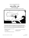
III. INSTALLATION OF CONSOLE
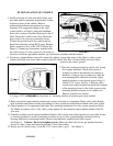
5. Install and route all video and audio cables, and
any other added component requirements to their
respective places in the vehicle. Refer to
component installation instructions for wiring
diagrams. The suggested routing of the video
system cable is as follows: Above the headliner
from video system to B-pillar. Rearward to the C-
pillar. Down the C-pillar to the floor. Route the
power lead to an accessory controlled source.
Connect the ground lead to the vehicle chassis.
Route the remaining wiring (RCA plugs, Remote
Sensor extension, etc.) to the VCP location. See
Figure 4. Connect per instructions included with
the video system. If video system if to be used as a
television, install an appropriate antenna per instructions included with the antenna.
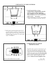
6. Construct a jumper harness that will connect the vehicle’s dome light wires to the lights in video system.
Connect the white wire from video system to the O.E. black/ blue wire. Connect black wire from video
system to the chassis ground.
7. Place the overhead console in vehicle and loosely
fit it against headliner. Check that console is
centered in vehicle and matches all contours of
headliner. Using an awl or similar tool, align the
rear mounting hole with hole in bracket. Apply
upward pressure to console and secure using (1)
one #8 x 3/4" screw. See Fig. 5. Release video
screen from locked position and mark the locations
of the mounting bosses in the video system on the
mounting bracket using an awl or similar tool.
Remove console from vehicle.
8. Using a 3/32” drill bit, drill (4) four holes in mounting bracket at locations previously marked.
9. Raise console into approximate position and connect all wiring to components. Route video cable through
hole in bracket and connect wiring and cabling to video system per instructions included with video system.
10. Check function of all components and lights. See operating instructions for video system operations check.
For further assistance, refer to the video system manual for the technical support phone number listed for
your area.
11. Carefully position console against headliner. Release video screen from locked position. Lower video screen
to viewing position for access to mounting locations in top of video system housing and align holes in
housing with holes in mounting bracket. Secure using hardware supplied with video system.
See Figure 5. Caution: Do not overtighten screws. Make sure that wires do not get pinched between
bosses on video system and mounting bracket. Close video screen.
12. Secure rear of console using (1) one #8 x 3/4" screw (item 1 pg 2). See Figure 5.
FIGURE 3
FIGURE 4
FIGURE 5