


VEHICLE PREPARATION:
1) Read the manual and get familiar with the electrical requirements and connections.
2) Prepare the vehicle by removing any interior trim necessary to gain access to the vehicle's wiring as well as all
areas where interconnecting wire harnesses will be located. The best location for the HR7DDPKG System
components is:
a. Monitors: Vehicle specific Headrest (NOTE: The M1 should be installed in the passenger
position most used. Check with the customer before installing this system.)
b. FM Modulator: Near the car radio.
c. System Main Cable: Under seats where M1and M2 are located.
3) Locate an accessory power source (+12VDC present when the ignition key is in the accessory and run posi-
tions. 0VDC should be present when the ignition key is in the OFF position), a constant power source (+12vdc)
at all times, regardless of the ignition key and a good ground. Generally, these wires can be found at the
ignition switch or fusebox. (NOTE: Installation of the large choke is only necessary if experiencing engine
noise.)
(NOTE:
Ensure that both the constant and accessory power is fused at the source. Failure to do so may result
in vehicle wiring damage.)
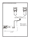
INSTALLATION: (see wiring diagram on page 4)
1) Run the wiring harnesses throughout the vehicle as necessary (Refer to the wiring diagrams on page 4.) Be
sure, that all the wiring is protected from sharp edges and is routed in such a manner that it will not be pinched,
when it is fully installed. Be sure to leave enough slack in the wiring at each component to allow sufficient
working room. Be sure to leave enough slack in the monitor cables to allow the headrest to move up or down,
and seat movement. Keep main harness and seatback harness away from the seat tracks
2) install the FM modulator in an area where there is access to the radio antenna connector. This may be behind
the radio or in a kickpanel.
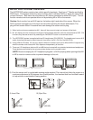
3) Install the Headrests:
a.Remove vehicle’s original headrests.
b.Hold the HR7DDPKG headrest above the seat and insert the two cables into the headrest support
tube holes. Make sure that the headrest is in the correct position (display facing the rear).
c.Route the cables through the seat back and out the bottom of the seat.
d.Place the headrest tubes into the support tube holes while pulling the cables to remove
the slack. Be sure to leave enough slack in the monitor cables to allow the headrest to move up or
down.
e.Carefully remove clear shrink tubing making sure not to damage wires inside. (see
1 next page.)
4) Connect the terminals of the system main cable to the corresponding 2 pin terminals of M1 and M2 at the
bottom of the seats verifying that the wire colors for each connector match the wire colors of the mating
connector .
(NOTE: Keep in mind that there are two groups of 2 pin connectors with 10 different wire colors. Be sure to
install the correct connector to the correct color wires. Failure to do this could cause damage to the electrical
component and or vehicle. On the main cable that attaches to the M2 harness there will be an unused connec-
tor (Green and Brown.)
5) Connect all the components together (electrically) and verify proper operation of all the system functions.
(NOTE: This is best done BEFORE reassembling the vehicle.)
6) After reassembling the vehicle, recheck the entire system to be sure it is functioning correctly. Make sure that
no wiring was pinched, or connected improperly during the final installation.
-3-