


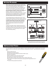
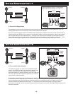


The inputs and controls for this amplifier are explained in the summaries below and reference the numbered call-outs above.
1.) CROSSOVER FREQUENCY SETTING - the internal
crossover frequency control setting of the amplifier can
be switched to either the “flat” frequency response
position or in a low-pass mode (passes only low
frequencies). On this amplifier, the choice is for either
100 Hz or 75 Hz low pass mode only. This unit is NOT
high-pass frequency capable.
2.) POWER “ON” LED - This light will turn on when the
amplifier receives a +12 volt turn on signal from the
radio in the vehicle. The input line to the “trigger”
connection must be properly connected to the radio’s
trigger line which is often also the power antenna line. If
the amp is properly wired, but the light does not turn on,
verify the trigger line is properly connected, is receiving
+12 volts, and the speaker outputs are not shorted to
themselves or ground in any way.
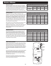
3.) INPUT GAIN CONTROL - This controls the gain
setting on the input of the amplifier. For high gain
settings ( 0.3 volts), this says that it takes ONLY 0.3
volts to drive the amp to full output. For low gain
settings (near 4 volts), this says that it takes nearly 4
volts to drive the amp to full output. If the amp is often
going into distortion at only moderate volume settings
on the radio, rotate this control towards the 4 volts
setting to reduce the distortion.
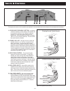
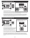
4.) HIGH LEVEL INPUTS - Should RCA cables not be
available from the radio you are able to tap onto the
audio signal from the high level speaker outputs of the
radio. This is most commonly used when the amp is an
add-on device such as for a subwoofer system.
5.) LOW LEVEL INPUTS - The more commonly used
inputs, these are connected to the standard RCA
outputs available on nearly all aftermarket radios today.
These lines are dedicated to left and right outputs of the
radio, be it for front or rear speaker installations. The
input gain settings of the amplifier (0.3 - 4 volts) are
referenced to these inputs.
INPUTS & CONTROLS
– 7 –
1 2 3 4 5
HIGH-LEVEL – INPUT
R
L
GAIN
MIN
MAX
+
+
-
-
GREEN
GREEN-BLACK
GREY-BLACK
GREY
(NOT USED)
LEFT (+)
LEFT (–)
RIGHT (–)
RIGHT (+)
HIGH-LEVEL – INPUT
R
L
GAIN
MIN
MAX
+
+
-
-
GREEN
GREY
LEFT (+)
RIGHT (+)
RADIO CHASSIS GROUND -OR-
COMMON SPEAKER GROUND
GREEN-BLACK
(NOT USED)
GREY-BLACK
(NOT USED)
"Floating Ground" Radio Outputs
"Common Ground" Radio Outputs
High Level (Speaker Input) Wiring