


Page 2 of 8 SA-365-10 Installation Instructions
05/24/10 CP5036A
TABLE OF CONTENTS
GENERAL DESCRIPTION....................................................................................................2
SPECIFICATIONS.................................................................................................................2
INSTALLATION.....................................................................................................................3
SAFETY PRECAUTIONS................................................................................................. 3
UNPACKING....................................................................................................................3
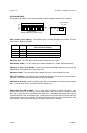
OPTION SWITCHES........................................................................................................4
MOUNTING...................................................................................................................... 5
ELECTRICAL CONNECTIONS........................................................................................ 5
OPERATION .........................................................................................................................6
POWER ON/OFF .............................................................................................................6
YELP - STANDBY - WAIL SELECTOR SWITCH.............................................................6
MANUAL / PHASER - HORN SWITCH ............................................................................ 6
AUXILIARY INPUT FUNCTIONS......................................................................................6
Horn Ring Cycler 2 (HRC2).......................................................................................6
SERVICE............................................................................................................................... 7
PROBLEMS......................................................................................................................7
PARTS and ACCESSORIES............................................................................................7
RETURNS.........................................................................................................................8
WARRANTY .....................................................................................................................8
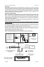
GENERAL DESCRIPTION
The SA-365 Siren Amplifier is designed for single 100W speaker use. The primary operating
modes are Yelp, Wail and Standby, selected by a 3-position rocker switch. Horn Override, push-
on/push-off Phaser operation in the Yelp and Wail modes, and Manual siren control in the
Standby mode are controlled by a momentary 3-position rocker switch. The unit features instant-
on allowing the unit to produce a tone instantly when a switch is activated. A DIP switch provides
options such as Two-Tone, disable tones, HRC2 operation, Auxiliary function, etc. The unit util-
izes short circuit, high voltage, and reverse polarity protection systems for maximum service life.
An output light indicates siren signal output for diagnostics and troubleshooting.
SPECIFICATIONS
NOTICE
Due to continuous product improvements, we must reserve the right to change any specifications and information,
contained in this manual at any time without notice.
Carson Manufacturing Co., Inc. makes no warranty of any kind with regard to this manual, including, but not
limited to, the implied warranties of merchantability and fitness for a particular purpose.
Carson Manufacturing Co., Inc. shall not be liable for errors contained herein or for incidental or consequential
damages in connection with the furnishing, performance, or use of this manual.
See www.carsonsirens.com for latest information.
Speaker Load Single 100W 11ohm
Input Current 8 AMPS (@14 VDC - single 100W speaker)
Standby Current 0 mA
Output Power 105 WATTS RMS MAX. (15 VDC - single 100W speaker)
Siren Frequency 700Hz - 1500Hz (Two-Tone and Horn = 435 & 585Hz)
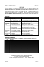
Tones / Cycle Rates Horn Wail Yelp Phaser Two-Tone
Cycle Rates 109 CPS 13 CPM 190 CPM 15 CPS 60 CPM
High Voltage Protection 16 - 18 VDC will cause siren output to cease, resume at normal voltage
Short Circuit Current 50 AMPS (supply circuit must be capable of supplying this for 1 second)
Operating Temp. -15° F to +140°F
Controls 3-position rocker selector switch (Yelp, Wail and Standby).
3-position momentary rocker switch (Horn and Manual/Phaser toggle).
Positive or Negative Auxiliary input.
8-position DIP switch option selector.
Connections (6-Pin Conn) Positive, Negative, (2) Speaker, and Auxiliary +/-.
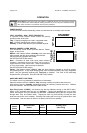
Size 4-1/2" Wide, 1-13/16" High, 4-13/16" Deep
Weight 3 LBS.
Input Voltage 10 - 16 VDC (negative ground)