


Page 8 of 15 SA-430-17 Installation and Operating Instructions
CP5010A 08/05/08
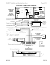
ELECTRICAL CONNECTIONS - Amplifier
Electrical connections to the amplifier are made using a terminal block plug located on the
amplifier. A label on the unit identifies each terminal function. You should install the plug on
the unit before wiring. If the unit needs service the plug can be easily removed without
unwiring. The power supply of the unit must be capable of delivering peak currents up to 50
amps for adequate short circuit protection and reliable operation. The preferred source is
directly at the vehicle battery. The amplifier is fused near connector.
Attach leads by stripping 3/8", inserting into connector and clamp by tightening screw. Make
sure the screw is tight and the wire can't be pulled out.
Failure to adequately tighten the screw can result in improper operation or burning the
connector and wire.
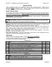
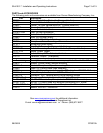
Wire Size and Termination - The diagram shows the minimum wire size used for each
connection, along with recommended lead color. If the wire is longer than 10 ft. use the next
larger wire size. The power lead pairs can be extended with single #10 AWG lead wire. Use
only high quality crimp connectors for installation on the vehicle.
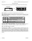
Optional Radio Input Connection - Connect one lead to each terminal of the radio speaker
or output connector. The input is isolated and polarity is not important. May need to set
RADIO VOLUME ADJUST on side of amplifier.
Optional Cutout Input Connection - The Cutout Input turns off any siren tone output when
activated, and remains off until a control is activated or changed. May need to set polarity.
See OPTION SWITCHES section for programming details.
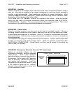
ELECTRICAL CONNECTIONS – Control Head
All control head leads can be extended with #22 AWG or larger lead wire.
Black: Negative - Connect to same ground or negative supply as amplifier.
Red: Positive - May be connected to +VDC supply. It is recommended that the lead be
connected to the accessory output of the fuse block. This provides additional protection of a
fused input to the control head.
Yellow: Lights - This lead may be connected to the dash lights or to the red power lead.
Connecting to the dash lights will turn on the panel lights whenever the dash lights are on.
When connected to the red lead, make sure that the ignition switch controls the power to that
connection. This prevents the panel lights from being continuously on.
White: Control - Connect white leads from amplifier and control head. Route this lead away
from the transmitter antenna lead to prevent R.F. interference being fed to the siren amplifier.
Green: Auxiliary Input - Used for Siren control. Performs same function as Siren button.
Connect to a normally open switch or to horn ring circuit. Circuit may connect to either positive
or negative. When connected to horn ring circuit, use a SPDT switch to connect horn ring to
either vehicle horn or to manual control circuit.
NOTE: Permanent disconnection of the vehicle horn is NOT recommended.
NOTE: Be sure to cut lead short if not used and insulate with electrical tape.