


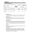
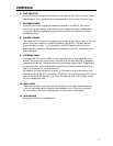

CONTROLS
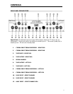
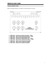
REAR PANEL PREAMPLIFIER
Special Note: The balanced input and output XLR connectors follow the ITT Cannon pin out
configuration. This pin-out calls for the shield to be wired to pin #1. The normal- phase (hot) is
wired to pin #2. Pin #3 is the inverted phase.
1. CINEMA INPUT FROM PROCESSOR – RIGHT RCA
2. CINEMA INPUT FROM PROCESSOR – RIGHT XLR
3. TAPE INPUT– RIGHT RCA
4. TAPE OUTPUT– RIGHT RCA
5. SERIAL NUMBER
6. TAPE OUTPUT– LEFT RCA
7. TAPE INPUT– LEFT RCA
8. CINEMA INPUT FROM PROCESSOR – LEFT XLR
9. CINEMA INPUT FROM PROCESSOR – LEFT RCA
10. XLR1 INPUT – RIGHT CHANNEL
11. XLR2 INPUT – RIGHT CHANNEL
12. AUX1 INPUT – RIGHT CHANNEL RCA
11