


CERWIN-VEGA! PROFESSIONAL
9
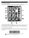
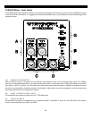
(C) SIGNAL/CLIP INDICATORS
Each of the three inputs is monitored by an indicator that provides status on the incoming audio signal. The SIGNAL
indicator is illuminated when there is an audio signal present with a level greater than -30dBu, approximately the lowest
level before a MUTE condition. The CLIP indicator is illuminated when the audio signal is clipping and adjustments must
be made to avoid amplifier shutdown and poor sound quality. Adjustments to prevent clipping are made by reducing the
input signal gain/level on the appropriate channel or reducing the volume level on your audio source, if possible.
(D) INPUT 1 & INPUT 2 INPUT JACKS
A combination input on each channel allows for either XLR or ¼” TRS cable types.
(E) INPUT 3 INPUT JACKS
A pair of ¼” TS unbalanced input jacks is provided on this channel for stereo connections such as a keyboard or media
device. Devices with RCA outputs can use these inputs with the appropriate cable or plug adapter. Both input jacks on
this channel are summed into one mono signal.
(F) THRU 1 & THRU 2
The balanced XLR outputs THRU 1 & THRU 2 are parallel connections to the respective INPUT 1 and INPUT 2. The level
controls for INPUT 1 & INPUT 2 will not affect the signal on the direct output connection.
(G) MIX OUTPUT
This is a balanced XLR output that is a sum of all three input channels. This output is not affected by changes to the
Main Volume knob or the custom features but is affected by the levels set on each channel level knob. This connection is
designed to provide an output which combines all three input channels together for connecting to another P1500X
powered speaker or a recording device.
(H) MAIN VOLUME KNOB & REMOTE VOLUME CONTROL
It is highly recommended to have the volume set to the minimal (MIN) level upon initial system start-up and it can be
adjusted two different ways. On the main volume knob, volume is increased in a clockwise rotation and decreased in a
counter-clockwise rotation. Another method to control the volume is by using the Remote connection (sold separately).
A removable three-terminal jack can be wired over long distances to a remote volume control device with a
corresponding connection.
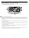
(I) INDICATORS
Three indicators provide operating condition status on the P1500X:
1) The POWER indicator (green) will illuminate when power is properly applied to the P1500X and the main power
switch is ‘ON’.
2) The LIMITER indicator (yellow) will illuminate when the P1500X automatically reduces the sound output to
prevent damage to the speaker. While the P1500X is producing sound, it is suggested to reduce the volume level
so the LIMITER indicator does not illuminate. Continuing use of the P1500X while this indicator is illuminated
may result in a protect condition where no sound can be produced. Note, upon initial power up the indicator
will blink. This is normal behavior as it will indicate the firmware version in the unit.
3) The PROTECT indicator (red) will illuminate when the P1500X automatically places itself into a condition where
sound output is shutoff. This condition may be the result of excessive limiting, an excessive heat condition, or a
low voltage condition. These conditions all can cause significant damage to the product.