


COUSTIC.COM
13
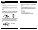
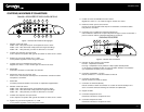
ADJUSTMENTS
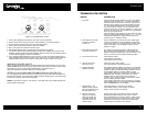
CROSSOVER SELECTION
The amplifier has built-in high-pass/low-pass filters for both front and rear channels that can be
defeated by sliding the switch to the OFF position.
1. When the high-pass is selected, the amplifier will be devoted to mid/tweeters.
2. When the low-pass is selected, the amplifier will be used to drive woofers/subwoofers.With
this setting, the optional R S can directly control the amplifier playback level.
3. When the filter is switched off, the amplifier is used as a full range amplifier.
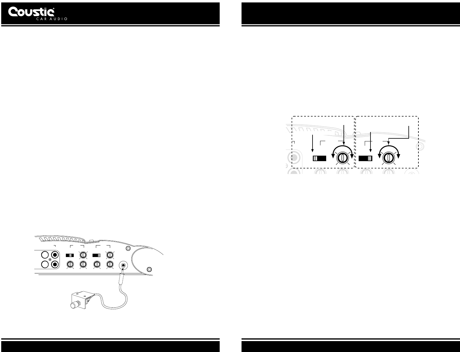
CROSSOVER FREQUENCY SELECTION
Both the high-pass and the low-pass section offer continuously adjustable crossover frequencies
between 30 Hz and 300 Hz. Adjust the setting according to your speaker component specifica-
tion or to your particular preference.
Figure 13: Crossover Frequency AdjustmentI
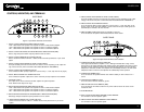
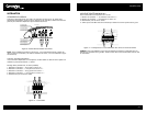
INPUT SENSITIVITY ADJUSTMENT
The Input Sensitivity Control is located on the Input Panel. The objective of input sensitivity adjust-
ment is to match the output of the source unit with the input of the amplifier. The output voltage of
individual source units can vary. For example, some source units have an output of 200 mV and
others have 5 Volts or more. To cater to these variations, the QE amplifier has an adjustable input
sensitivity level that ranges from 100 mV to 5 volts.
Adjusting this control requires some experimenting. Basically, you want all the gain at the begin-
ning of the system, NOT at the end (amplifier). Turn your headunit UP and keep your amplifier
gains at the minimum possible setting (counter-clockwise). This will give you the best sound and
signal-to-noise ratio.
Besides better sonic reproduction, proper input sensitivity also helps to prolong the reliability span
of your amplifier by eliminating excessive internal temperature generated by incompatible source
unit output and amplifier input.
Note: Turning the input gain UP does NOT indicate MORE power. Just MORE noise. The input
gain control IS NOT a power control. REMEMBER that the input gain control has nothing to do
with the power output of the amplifier
FRONT
REAR
REMOTE
SUB LEVEL
MODE
HPF OFF LPF
FREQ
30 300
60 180
BOOST
MODE
HPF OFF LPF
FREQ
30 300
60 180
BOOST
REAR
UTS
Front:High-Pass Selected
Front:High-Pass
Frequency adjustment
Rear:Low-Pass
Frequency adjustment
Rear:Low-Pass Selected
SENS SENS
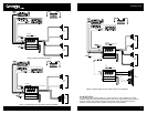
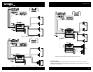
CONNECTING AMPLIFIER POWER WIRE TO THE BATTERY
Note: Power cables are as important as battery capacity. Use only high quality power cables of
gauge size AWG 8 (AWG 4 for the 481QE) or larger for installation. YOU CAN NEVER HAVE
TOO BIG OF A POWER/GROUND WIRE!
Run the power cable through the interior of the vehicle connecting one end to the amplifiers B+
terminal and connecting the other end to the positive post on the battery. Be sure not to run the
power cable together with the audio cables as it would invariably cause radiated engine noise in
your audio system. If possible, run audio cables on one side of your car and power cables on the
other. Never route these wires underneath the vehicle body.
It is also advisable to install a circuit breaker/fuse 18” from the battery. This would effectively
lower the risk of the power cable catching fire should a short circuit occur in the audio system. A
circuit breaker or fuse with 50% of the main batteries’ amp hour rating is recommended. Going
larger in circuit breaker or fuse value means that you have NO protection. DO NOT over fuse!
Fuses on the amplifier DO NOT protect the amplifier, they protect the car.
CONNECTING AMPLIFIER GROUND WIRE TO THE VEHICLE CHASSIS
Find a good ground spot on the vehicles chassis and remove the paint to reveal bare metal at the
contact point. Attach the ground wire to that contact point and connect the other end of the
ground wire to the GND terminal of the amplifier.
TERMINALS, LUGS AND CONNECTORS
High current terminals, lugs and/or connectors are also required to ensure a safe and sure electri-
cal connection and conduction.
CONNECT THE AMPLIFIER REMOTE CONTROL
Connect the remote REM terminal of the amplifier to the remote output terminal of the source unit
to establish amplifier remote on/off through the power on/off of the source unit. If the source unit
does not provide a remote output, connect to its power antenna lead or other switched 12-volt
source, e.g. ignition switch.
RECONNECT THE BATTERY GROUND TO THE VEHICLE CHASSIS
Double check all the previous installation steps, in particular, the wiring and component connec-
tion. If everything is in order, complete the installation by reconnecting the battery ground to the
vehicle chassis.
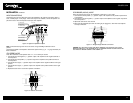
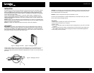
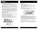
OPTIONAL REMOTE SUBWOOFER GAIN CONTROL (R S)
If the optional remote subwoofer level control (model R S) is used, connect the plug of the R S to
the port on the end panel of the amplifier.
Figure 12: Remote Subwoofer Gain Control (481QE only)
FRONT
REAR
REMOTE
SENS
MIN MAX
MODE
HPF OFF LPF
FREQ
30
300
60
180
0
+18
BOOST
SENS
MIN MAX
MODE
HPF OFF LPF
FREQ
30
300
60
180
0 +18
BOOST
INPUTS