


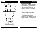
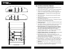
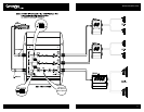

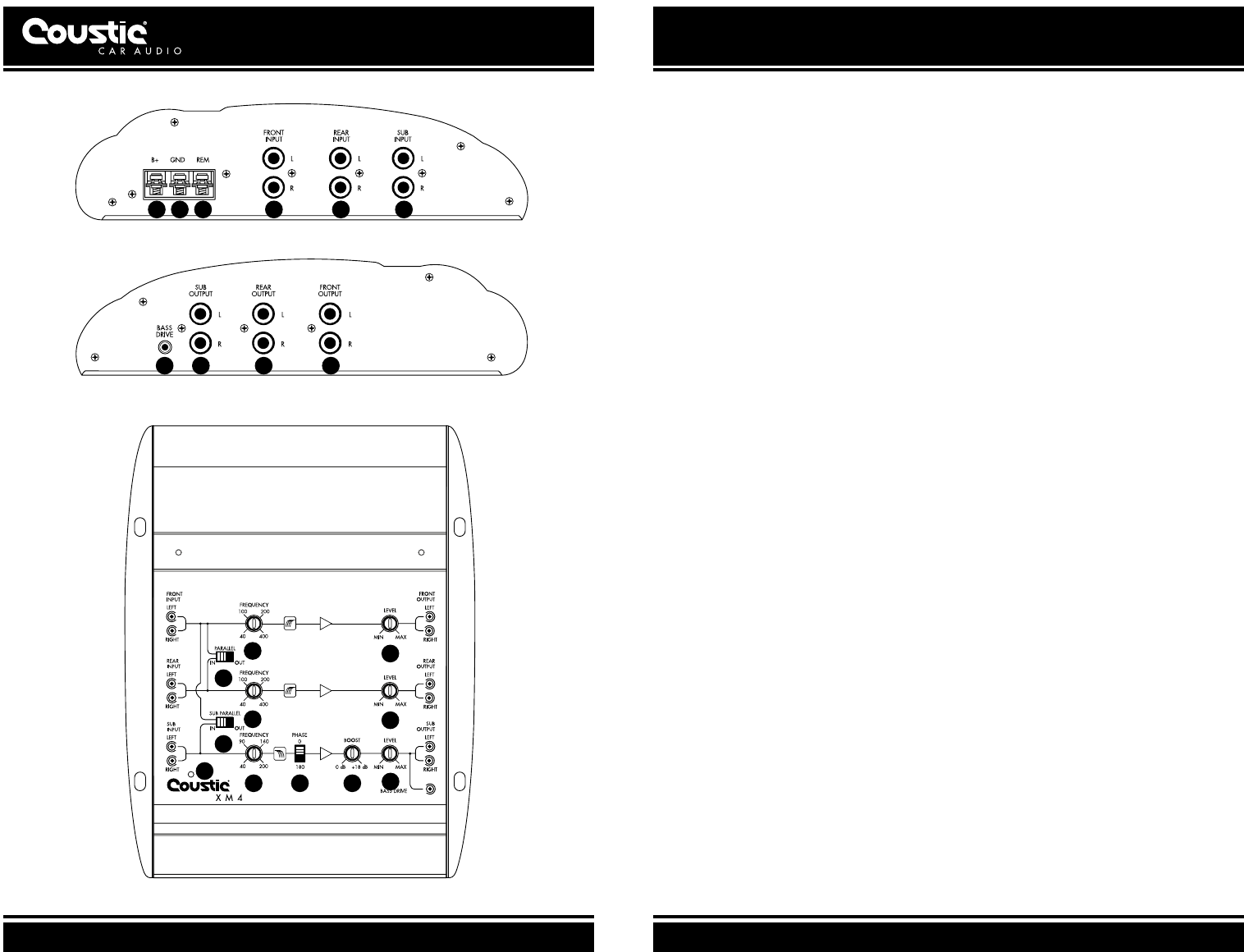
XM4: CONTROLS, INDICATORS & TERMINALS
1 Power Input Terminal (B+) – Connects to the positive terminal of your
vehicle battery or other constant +12V source
2 Ground Input Terminal (GND) – Wires to the vehicle’s chassis ground
3 Remote Turn-on Input Terminal (REM) – Connects to the remote
control wire or antenna lead of the source unit for remote ON/OFF
4 Front Line Level Inputs – Connects to the front channel RCA output
of the source unit
5 Rear Line Level Inputs – Connects to the rear channel RCA outputs
of the source unit
6 Subwoofer Line Level Inputs – Connects to the subwoofer channel
RCA outputs of the source unit
7 Bass Drive™ Remote Sub Gain Control Port – Connection for optional
R S remote to control subwoofer output levels
8 Subwoofer Line Outputs – Connects to the dedicated subwoofer ampli-
fier left/right inputs
9 High Pass Line Outputs – Connects the crossover’s front and rear high
pass outputs to the dedicated high frequency amplifier inputs
10 Parallel Input Switches – “IN”: Set each switch to the “IN” position
when the source unit does not supply rear or subwoofer channel out-
puts. “OUT”: If the source unit has independent front, rear and/or
sub channel outputs, set each switch to the “OUT” position
11 High-Pass Frequency Selectors – For selection of high-pass crossover
frequency between 40Hz and 400Hz, 18dB/Octave
12 Subwoofer Frequency Selector – For selection of the low-pass crossover
frequency between 40Hz and 200Hz, 36dB/Octave
13 Sub Phase Control Switch – Positioning the switch to the “180”
position shifts the subwoofer output signals 180 degrees out of phase
relative to the front and rear output signals
14 High Pass Output Level Controls – Adjusts the high pass output signal
15 Sub Bass Boost EQ – Centered at 45Hz with 18dB of adjustment, this
feature will enhance the low frequency output of your audio system
16 Subwoofer Output Level Control – For adjusting the low pass output
signal level
17 Power Indicator – This indicator lights up when the internal switching
power supply is activated and the unit is operational
WWW.COUSTIC.COM
9
1 2 3 4 5 6
7 8 9 9
10
10
11
11
12 13
14
14
15
16
17
XM4 INPUT PANEL
XM4 OUTPUT PANEL
XM4 CONTROL PANEL