


WWW.COUSTIC.COM
11
Note: Please check with your vehicle’s manual to see if special tools are
necessary for working on your particular vehicle.
Check and make sure the vehicle’s main battery and/or auxiliary battery, if
any, is/are in good working condition and has sufficient capacity to run the
electrical components of the vehicle plus the complete audio system.
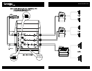
The XM series crossovers are designed for use in 12 Volt NEGATIVE
GROUND electrical system ONLY. Installing the units in a vehicle with positive
ground electrical system could result in serious damage to the electronic
crossover, other audio components and/or the vehicle’s electrical components.
If your vehicle happens to run on a positive ground electrical system, please
consult your Coustic dealer for specific instructions on installation.
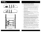
LOCATION
• Select a mounting location that is easily and conveniently accessible,
e.g. inside the trunk.
• To avoid damage to the unit, keep the crossovers away from any heat
source (such as the engine or any heat-generating ducts).
• Leave at least 6" clearance above the unit to allow easy adjustment.
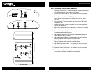
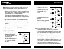
MOUNTING
• Place the XM series crossover at the desired location and use it as
a template to determine the exact position of the mounting holes.
• Mark the mounting holes with a felt pen, and put the crossover aside.
• If the mounting surface is carpeted, cut out small circles of the carpet
and padding around the four mounting holes to expose the metal
underneath.
• Use a center punch to ensure drilling the exact position for the screws.
Drill four (4)
1
⁄8” pilot holes. DO NOT BEGIN DRILLING UNTIL YOU
HAVE PUT THE CROSSOVER ASIDE. USING THE CROSSOVER AS A
DRILLING GUIDE MAY CAUSE IRREPARABLE DAMAGE TO THE UNIT.
• Mount the XM series crossover with the Phillips head sheet metal
screws and steel washers provided. (It is best not to tighten the screws
to the maximum at this stage, since you might want to change the
position at a later stage.)
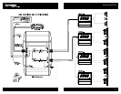
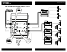
INSTALLATION
FOR SAFETY, DISCONNECT THE BATTERY GROUND BEFORE INSTALLATION.
Caution: Please follow all the installation recommendations and instructions
in this manual. Installing and/or using the XM series electronic crossovers
in methods other than those outlined herein may reduce the performance
capability of the crossovers. Any such installation or usage may render the
product warranty void.
PREPARATION
Before wiring and connecting the XM2 or XM4, please read the entire manual.
Mark down the accessories, tools required and important points as you go
through this manual. Have all the necessary accessories, hardware and tools
on hand. The following basic tools are required:
• Electric hand drill with assorted bits
• Screwdrivers (Phillips and flat head)
• Pliers
• Wire cutters
• Wire strippers
• Sharp knife
• Crimping tool
• Electrical tape or heat shrink tube for professional finish
• Soldering Iron (propane torch type) with solder
• Nylon tie wraps
• Volt/Ohm meter