EXPLANATION OF FEATURES AND CONTROLS
Refer to Figure A
1) Power Switch: This three position switch controls the power status of the sub-
woofer.
Off: Turns the unit off.
Auto: Places the unit in the standby mode, in this mode the subwoofer will auto-
matically turn on when an audio signal is applied to either the high or low level
inputs.
On: Turns the unit on regardless of whether a signal is present or not.
2) Subwoofer crossover: This rotary control adjusts a variable low pass filter to
set the upper frequency at which the output of the subwoofer begins to roll-off.
Continuously variable from 40Hz to 180 Hz, it matches the upper frequency char-
acteristics of the subwoofer to the low frequency response of the main stereo
speakers. Recommended setting 180Hz.
3) Line level input: These RCA phono jacks accept a line level full range signal
from the preamplifier output of a receiver or preamplifier. This full range signal is
processed and amplified to power the subwoofer.
4) Speaker level input: These spring loaded terminals for speaker wire accept a
stereo, speaker level, full range signal from a receiver or power amplifier. This
signal is processed and amplified to power the subwoofer.
5) Fuse: For continued protection replace fuse with same type and size listed.
6) Level control: This rotary control adjusts the level of the subwoofer and is used
to balance its volume with that of the main stereo speakers.
7) Status LED: This two color light emitting diode shows the status of the sub-
woofer electronics. "Red" indicates that the amplifier is plugged in and the power
switch is either off or in standby mode with no input signal present. "Green"
indicates that the amplifier is operating with signal present at the input from the
preamplifier, receiver, or power amplifier.
8) Speaker level output: These terminals supply full range signal to the front satel-
lite speakers.
WIRING AND CONNECTIONS
Turn off all power to your subwoofer and other equipment before making
any connections.
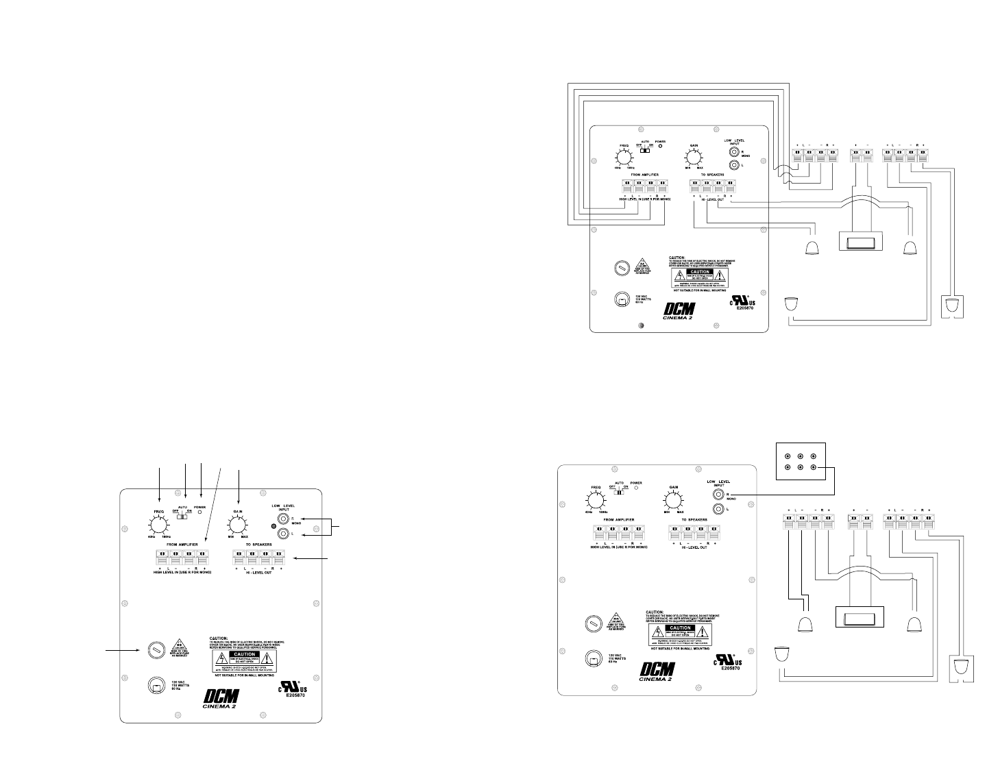
Installation using speaker level inputs (Figure B).
FIGURE B
FRONT CENTER SURROUND
A/V Receiver or Amplifier
RIGHT
FRONT
LEFT
FRONT
LEFT
REAR
RIGHT
REA
R
CENTER
FRONT
+ -
+ -
+ -
+ -
+ -
Installation with A/V amplifiers and receivers that have 5.1 channel line level
output (Figure C).
FIGURE C
FRONT CENTER SURROUND
A/V Receiver or Amplifier
RIGHT
FRONT
LEFT
FRONT
LEFT
REAR
RIGHT
REA
R
CENTER
FRONT
+ -
+ -
+ -
+ -
+ -
OUTPUTS
SUB


