


© 2008 Directed Electronics. All rights reserved. 9
AMPLIFIER WIRING
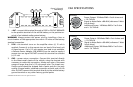
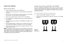
Power Connections
Power connections accept up to 4 AWG wire.•
4 AWG power and ground wire recommended for optimal per-•
formance.
Connect 12V+ to the battery through fuse holder. This connec-•
tion provides +12V main power to the amplifier.
Power wire must be fused no more than 12” from battery.•
Ground amplifier to a good chassis ground as close as possible to •
the amplifier.
Recommended fuses are 50A for the XTR2502, and 100A for the •
XTR5002.
Connect REM terminal to remote turn-on lead from source unit. •
This connection provides +12V power to turn-on the amplifier.
Add extra ground wire between the negative terminal of the •
battery and the chassis.
NOTE: The addition of a ground wire from the battery to the chassis
of the vehicle improves the ability of the battery to supply power to
the amplifier. This is recommended because the current delivery of the
factory electrical system was designed only to accommodate electron-
ics supplied by the auto manufacturer.
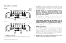
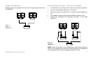
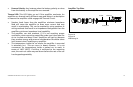
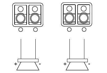
Speaker Connections XTR2502 and XTR5002
The Orion XTR2502 and XTR5002 amplifiers offer one positive and one
negative output terminal for ease of connecting channel 1 and/or 2
outputs to the speakers. The amplifiers are stable to 2Ω per channel.
See diagrams below.
One Channel/Two Channel Configuration
Lowest recommended impedance is 2• Ω stereo.
Outputs can be configured for high-pass, low-pass, or full range •
operation.
Figure 10
Figura 10
Abbildung 10
L CH
+
_
+
_
R CH
L CH
+
_
+
_
R CH
L CH
+
_
+
_
R CH