


© 2008 Directed Electronics. All rights reserved. 10
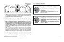
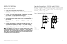
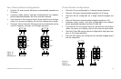
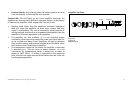
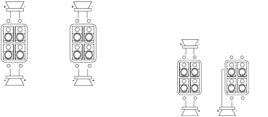
Four Channel Stereo Configuration
Channel 1/2 and channel 3/4 lowest recommended impedance is •
2Ω stereo.
Crossover mode, output, and gain configurations are indepen-•
dently adjustable between the front and rear channels.
Two-channel or four-channel input can be used for this configu-•
ration. For source unit fading, use the four-channel input mode.
Channels 1/2 and channels 3/4 outputs can be individually config-•
ured for highpass, low-pass, or full range operation.
Figure 10
Figura 10
Abbildung 10
1CH
CHANNEL 1
BRIDGED
CHANNEL 2
CHANNEL 3/4
2CH
+
_
+
_
3CH
4CH
+
_
+
_
1CH
CHANNEL 1
CHANNEL 2
2CH
+
_
+
_
3CH
4CH
+
_
+
_
1CH
2CH
+
_
+
3CH
4CH
+
_
+
_
_
1CH
2CH
+
_
+
3CH
4CH
+
_
+
_
_
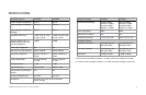
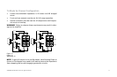
Three Channel Configuration
Channels 1/2 are configured for 2-channel stereo operation.•
Channel 1/2 lowest recommended impedance is 2• Ω stereo.
Channels 3/4 are configured for a single channel bridged out-•
put.
Channel 3/4 lowest recommended bridged impedance is 4• Ω.
Crossover mode, output, and gain configurations are indepen-•
dently adjustable between channels 1/2 and 3/4.
Two-channel or four-channel input can be used for this configu-•
ration. For source unit fading, use the four-channel input mode.
Channel 1/2 and 3/4 outputs can be configured for high-pass, low-•
pass, or full range operation.
Channel 3/4 outputs are configured for summed bridged opera-•
tion for subwoofer
Figure 11
Figura 11
Abbildung 11
1CH
CHANNEL 1
BRIDGED
CHANNEL 2
CHANNEL 3/4
2CH
+
_
+
_
3CH
4CH
+
_
+
_
1CH
CHANNEL 1
CHANNEL 2
2CH
+
_
+
_
3CH
4CH
+
_
+
_
1CH
2CH
+
_
+
3CH
4CH
+
_
+
_
_
1CH
2CH
+
_
+
3CH
4CH
+
_
+
_
_