


© 2008 Directed Electronics. All rights reserved. 3
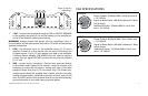
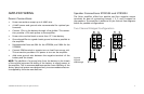
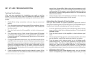
END PANEL LAYOUTS
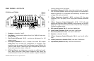
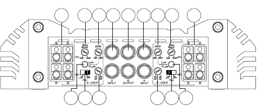
XTR2504 and XTR5004
1 2
3
4 5 9
11 12
13
10
14 15
1 2
3
6
8
7
Speakers - 1. channels 1 and 2
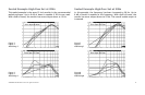
Bass Boost - 2. continuously adjusts from 0 to 18dB of boost cen-
tered at 45Hz
Gain Control (Channels 1 & 2) - 3. continuous adjustment for full
power output
RCA Input (Channels 1 & 2) - 4. accepts Low Level RCA Inputs
(400mV-8V) from a head unit, preamplifier, or equalizer. XTR
amplifiers can also accepts High Level Speaker Inputs (200mV-4V)
from an OEM stereo. These inputs are configured by the Input
Mode switch position (refer to item 6)
RCA Line Output - 5. provides easy connection to additional ampli-
fiers. Note that some OEM stereo headunits may sense the
attached load and may turn off their speaker outputs if expected
load conditions aren’t achieved
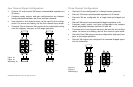
Input Mode (Channels 1 & 2) - 6. when the switch is out, the ampli-
fier will accept speaker level and high output RCA connections.
When this switch is in, it provides extra sensitivity for lower input
voltage RCA (refer to item 4)
X-Over (cross-over channels 1 & 2) - 7. activates LPF (low pass
crossover), FLAT (all pass), or HPF (high pass crossover) selection
switch
X-Over Frequency Control (channels 1 & 2) - 8. FLAT (all pass)
adjusts the frequency (50Hz–2000Hz) of the crossover for the HPF
(High-Pass Frequency Control) and the LPF (Low-Pass Frequency
Control) variable control
RCA Input (Channels 3 & 4) - 9. see item 4 definition
Gain Control (Channels 3 & 4) - 10. see item 3 definition
Bass Boost (Channels 3 & 4) - 11. see item 2 definition
Speakers - 12. channels 3 and 4
X-Over Frequency Control (Channels 3 & 4) - 13. see item 8 defini-
tion
X-Over (cross-over, channels 3 & 4) - 14. see item 7 definition
Input Mode (Channels 3 & 4) - 15. see item 6 definition
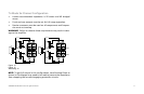
Figure 1
Figura 1
Abbildung 1