


69
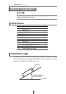
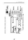
Mounting instruction
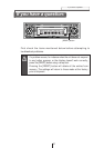
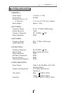
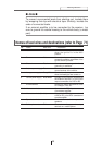
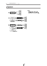
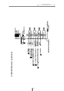
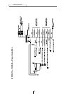
Names of lead wires and destinations (refer to Page 71)
No. Name Wire color Destination
1 ACC Red Connect where the power comes on
when the ignition is in the ACC
position.
2 B+ Yellow Connect where the power is
constantly available, regardless of the
ignition switch's position.
3 Ground Black Connect where good body
grounding is available.
4
Antenna power supply
Blue Connect to the automatic-antenna
control terminal of the vehicle.
5
Lamp power supply
Orange/White
Connect to where power comes on
when the headlights are turned on.
6
Control power supply
Blue/White
Connect to the control terminal for
the external amplifier, or to the RCA
output connectors of a DSP or EQ.
7 E-LAN terminal Connect to the E-LAN terminal of the
CD changer, DSP, etc.
8 & 9
Line-out terminals Connect to the RCA input connectors
of an external amplifier.
10 Line-out terminals (
Nonfader)
Connect to the RCA input connectors of
a DSP or EQ, or the RCA connectors of
a woofer amplifier.
11 Speaker terminals Connect them to their respective
speakers.
12
Cellular phone mute
Pink Connect to the ground output
terminal on a mobile phone.
O Note O
To prevent unconnected leads from shorting out, insulate them
by wrapping their tips with electrical tape. Similarly, insulate the
ends of connected leads.
If an external amplifier is to be connected to the receiver, be
sure to ground its outside housing to the vehicle body (a metal
part).