


DVI DA2 and DVI DA4 • Installation and Operation
2-9
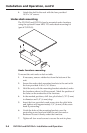
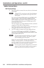
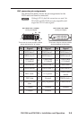
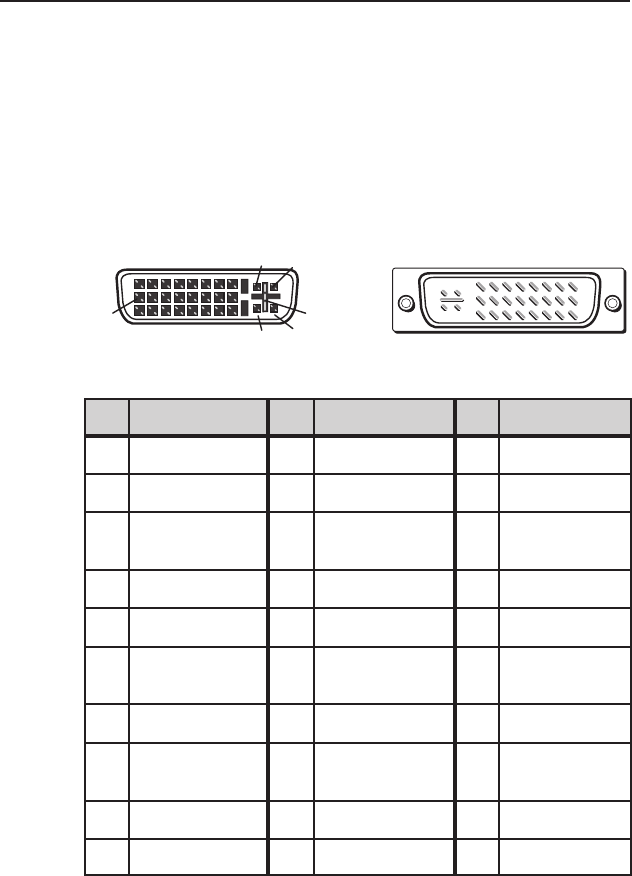
DVI connector pin assignments
The illustration below shows the pin assignments for the
DVI-I male and female connectors.
N
Although DVI-I dual link connectors are used, the
DVI DA2 and DVI DA4 are only compatible with
single-link DVI-D video signals.
Pin Signal
1
TMDS data 2–
TMDS data 2+
TMDS data 1–
TMDS data 1+
DDC clock +5 V power
DDC data TMDS clock+ Ground
Analog vertical
sync
TMDS clock– Hot plug detect
TMDS data 0–
TMDS data 0+
TMDS data 4-
TMDS data 4+
TMDS data 3-
TMDS data 3+
TMDS data 5-
TMDS data 5+
TMDS data
2/4 shield
TMDS data
1/3 shield
TMDS data
0/5 shield
TMDS clock
shield
Pin Pin Signal Signal
2
9
10
17
4 12 20
5 13 21
6 14 22
7 15 23
81624
18
3 11 19
C1 C3 C5
C2 C4
Unused
Unused
Unused
Unused
Unused
Three rows of 8 pins and two contacts
above and below the flat blade.
DVI-I Dual Link - Male
(analog and digital)
Three rows of 8 holes and two contacts
above and below the "
+" socket.
DVI-I Dual Link - Female
(analog and digital)
1
9
8
17 24
C3 C4
C1 C2
C5