


IN3252HR • Internal Jumper Settings
IN3252HR • Potentiometer Adjustments
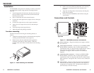
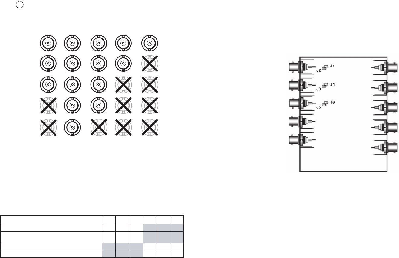
Input coupling jumpers (J1, J4, and J6)
To insure the best picture quality, inputs are DC coupled as a
factory default.
If the source device has a high DC offset that causes picture
distortion and/or instability, change the jumpers to AC
coupling.
Figure 6 — Board view of jumpers
Potentiometer Adjustments
With an oscilloscope
1. Feed a grayscale signal from an Extron VTG 300/400 or
other A/V test generator to the input of the IN3252HR DA.
2. Remove the far end of the green output cable from the
display and connect it to the oscilloscope with 75 ohm
termination.
3. Adjust the green gain control to achieve 0.7 Vp-p for the
white bar of the test pattern.
4. Repeat steps 2 and 3 for the red and blue channels.
5. Adjust the peaking control by connecting the oscilloscope
back to the far end of the green output cable and adjusting
the peaking potentiometer until no overshooting or round
corners appear on the test pattern.
6. Plug the far end cables back to the display device.
54
5
Peaking control — Rotate to adjust the amount of high
frequency boost added to the video signals to compensate for
long cable runs.
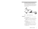
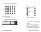
G
RGBHV
RGBS
RGsB,
RsGsBs,
Component
R B
S-Video
Composite
H/S
V
Figure 4— BNC connectors
Internal Jumper Settings
Input termination jumpers (J2, J3, and J5)
In normal operation (factory default) the inputs are terminated
internally. To provide a passive loop-through signal for a local
monitor or extended DA system with 75 ohm input impedance,
jumpers J2, J3, and J5 must be changed from closed to open (see
figure 5 below).
Input is terminated to 75 ohms (loop-through not used)*
AC coupling
Input is unterminated (High Z) (loop-through connected to a
local monitor or another amplifier)
Configuration
*Factory default settings
DC coupling
J2 J3 J5 J1 J4 J6
Closed*Closed* Closed*
OpenOpenOpen
Open Open Open
Closed* Closed*Closed*
Figure 5 — Jumper table