


Installation and
Operation
This section provides information pertaining to the installation and operation of the
MTP DA4 and MTP DA8, including:
• Connections
• Power Supply Wiring
• TP Cable Termination
• Front Panel Power Indicator
• Skew Delay Problems
Connections
ATTENTION: Do not connect these devices to a computer data or telecommunications
network.
MTP DA4
1234
1234A
OUTPUT MUTE
12V
POWER
+
-
MTP DA8
A/V INPUT
12345678
1234 5678A
OUTPUT MUTE
0.93A MAX
12V
POWER
+
-
A/V OUTPUTS
A/V INPUT
0.93A MAX
A/V OUTPUTS
1 2 3 4
1 2 3 4
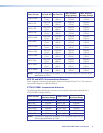
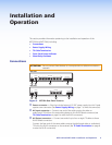
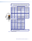
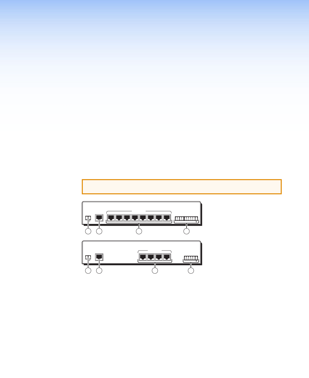
Figure 3. MTP DA Rear Panel Features
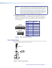
a Power connector — Plug the included external 12 VDC power supply into this 2-pole
captive screw connector (see Power Supply Wiring on page 7 to wire the connector).
b AV Input connector — Connect one end of the cable carrying the video or
audio/ serial TP link from the transmitting device to this RJ-45 female connector (see
TP Cable Termination on page 8 to wire the RJ-45 connectors).
c AV Output connector — Connect one end of up to four or eight TP cables to these
RJ-45 female connectors.
Connect the free ends of the same cables carrying the distributed video or audio/serial
TP link to the RJ-45 connectors on the receivers (see TP Cable Termination on page 8
to wire the RJ-45 connectors).
6MTP DA4 and MTP DA8 • Installation and Operation