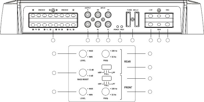
CA-DA41400 - CONTROL DESCRIPTIONS
1 2 3 4 5 6 7 8 9
10
11
12 16
15
14
13
1. SPEAKER OUTPUT:
Connect your speakers to these terminals.
2. RCA OUTPUT:
Use these RCA connectors to connect to a secondary
amplier. This output is a pass-thru connection derived
from the RCA input connectors so that the signal level and
frequency response is the same as the original input signal.
3. REAR RCA INPUT:
Connect these RCA connectors to a head unit with a rear low
level output connection.
4. FRONT RCA INPUT:
Connect these RCA connectors to a head unit with a front low
level output connection.
5. POWER AND STATUS LED’S:
This displays “green” if the amplier has been correctly
powered up & ‘red’ if any faults are present.
6. FUSES:
Please ensure the correct type of fuse is tted.
For CA-DA41400 2 x 40A fuses.
7. +12V CONNECTION:
Connect directly to the vehicle battery positive (+) terminal via
a 4 gauge power cable, with an inline fuse or circuit breaker
at the battery end. NOTE: This is the last wire to connect up
during installation. Damage could result if this is not done.
8. REMOTE TURN-ON CONNECTION:
This terminal is for turning the amplier on and off. The
remote input requires a switched positive (+12V) to power
‘ON’ the amplier. This can usually be found on the rear of
the head unit in the form of a remote output. If not available
you can wire to the ACC position on the ignition key.
9. GROUND CONNECTION:
Connect directly to the vehicle’s chassis via a 4 guage power
cable. NOTE: This is the rst wire to connect up during the
installation.
10. REAR LEVEL:
This allows level adjustment of the front input signal. Use this
control to directly match the head unit to the amplier. To
set this control correctly, turn the amplier level to MIN and
the head unit to 3/4 volume, with the bass and treble on zero,
then slowly turn up the level control towards the MAX end of
the control. NOTE: If the sound becomes distorted, turn this
control down.
11. BASS BOOST:
The Bass Boost is a variable control to increase the level at
45Hz from 0 - +12dB of gain. Adjust this control with extreme
care.
12. FRONT LEVEL:
This allows level adjustment of the rear input signal. Use this
control to directly match the head unit to the amplier. To
set this control correctly, turn the amplier level to MIN and
the head unit to 3/4 volume, with the bass and treble on zero,
then slowly turn up the level control towards the MAX end of
the control. NOTE: If the sound becomes distorted, turn this
control down.
13. REAR FILTER FREQUENCY:
This sets the crossover frequency point for the rear lter
between 32Hz and 320Hz. NOTE: Failure to correctly set
could result in speaker damage.
14. REAR FILTER SELECTION:
This switch selects the type of lter used for the rear audio
signal. Either Low Pass, High Pass or Full Range can be
selected. The Low Pass lter is designed to lter out all mid
to high frequencies that only full range speakers should
produce. The High Pass lter is designed to lter out all
low frequencies that only subwoofers should produce. Full
Range allows all frquencies.
15. FRONT FILTER SELECTION:
This switch selects the type of lter used for the rear audio
signal. Either Low Pass, High Pass or Full Range can be
selected. The Low Pass lter is designed to lter out all mid
to high frequencies that only full range speakers should
produce. The High Pass lter is designed to lter out all
low frequencies that only subwoofers should produce. Full
Range allows all frquencies.
16. FRONT FILTER FREQUENCY:
This sets the crossover frequency point for the rear lter
between 32Hz and 320Hz. NOTE: Failure to correctly set
could result in speaker damage.


