


1.62K 604Ω 1.21K
1.21K
BoRo Go GAINM+ ENA
IN
BG
IN
R
IN R
R
R
G
A- BL
4-7VDC
5-9Vpp 61,B4
Vs
U
Blanking & Beam Current Limit
R
VC
4
RED
INPUT
VC
3
GND
0VDC
56V 28,D3
Hs
6
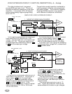
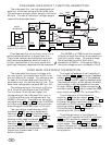
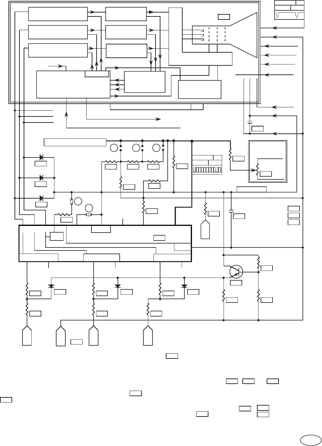
5.6V to 1.1V, NEGATIVE ANALOG, DC COUPLED, VIDEO INTERFACE CIRCUIT DESCRIPTION.
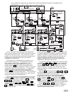
SOCKET BOARD
127V TC8
Feedback
V
Sync
CRT
Auto
Bright
Beam current
Feedback
Beam current
Feedback
Beam current
CRT Auto Bias
Beam
Current
Buffer
B+G+R=∑
Red Video Amp.
Green Video Amp.
Blue Video Amp.
ABA
TC 3 Blue
TC5 Green
TC7 Red
TC 6TC 10
SOCKET BOARD CONNECTOR (TC) 206
800
ARC PROTECT
100uF
209
+
10
4
TTL
BL
B
GND
Controls XRC5346A
R
B
241
16 13 5 12396 11
0
VC
11.5V-12.5V
VIDEO GAIN
LINE
GND
+12V
293
228
0Ω, CS=.30"
267
100uF
260 244 245
076
1.62K
S
T
2.7K
064
258
0Ω
12V
084
086
FDH400
213
FDH400
FDH400
+12V
+
485
1K
RC2
062
1K
Remote
Control
+12V
M. GAIN
GND
PCB
1N4148
271
278
1N4148
270
277
1N4148
268
276
301Ω
340Ω 301Ω
340Ω 340Ω
301Ω
236
218 266
5
VC
G
GREEN
INPUT
GND
292
21 1415 7 8
Vertical O/S or Delayed Vertical O/S.
End Vertical Blanking
GND
+12V
+16V
+127V
Filament
Fil. Ret.
Screen
Focus
EHT
TC11
TC12
4.7K
239
+12V
274
PN2222
273275
272
+12V
3.92K
2.15K1K
3.5V
B
VC
BLUE
INPUT
Video
Connecter
TC1 +16V
TC4 +12V
TC2 GND
HSync
FIL.
P
G
268
270
271
In each of the video interface circuit configurations,
current from the interface circuit is converted to a
voltage at the CRT cathodes. The simplest current
path is accomplished by the negative analog video
interface configuration.
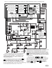
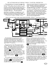
The voltage drop across the input resistors
278 and
236 , for the red channel, is the current which drives
the video amplifiers when the video gain line is at
8.2 volts. For a lower gain line voltage, part of the
current is directed to the +12 volt line. During blanking
all the input current flows to the +12 volt line.
and there is no video amplifier output. For the red and
green channels, a 1 volt change at the video input
produces a 15 volt change at the video amplifier output.
For the blue channel this change is 18 volts but resistor
265 subtracts the equivalence of .6 volts from the input
which results in the same saturated color as the red and
green channels.
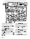
The clamp diodes
271 , 270 , & 268 limit the
maximum current to the video amplifiers. This avoids
over driving the video amplifiers when undershoots at
the input cables are present. The clamp reference
voltage is set by resistors
272 , 273 , and buffer
transistor 274 . Load resistor 275 stabilizes this
buffered clamp voltage.
Note:
65
278
236
265
271 268
270
274
273
272
275
The clamp
diodes are
installed
backwards with
respect to the
PCB legend.