


910111213
Retrace
Booster
GND
Boost
Drive
Vert.
Out
Thermal Protection
LA7838
Vertical
Deflection
377
603
601
607
4.7Ω
610
3.3Ω
608
4.7Ω
609
606
602
380
470uF
605
1.2Ω
604
611
FR205
TIP31A
+24V
+
TIP31A
TIP32A
FR205
382
1N4007
8
+24V
605
604
607
606
609
608
610
611
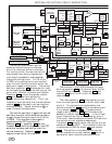
E
C
B
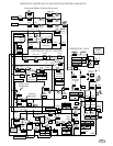
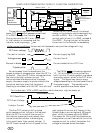
Vertical Amp. PCB
PNP
NPN
NPN
601
602
603
612, LA7838
CPB1615
E
C
B
E
C
B
135791113
PCB View;
Foil Side.
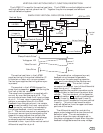
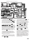
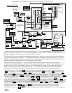
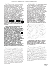
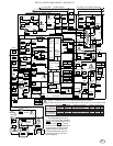
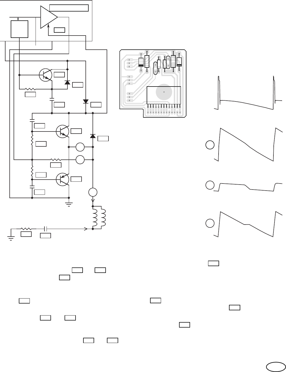
The output of the LA7838 is connected to the yoke by a 3.3Ω resister at 610 . It also drives the
bases of transistors 601 and 603 through 4.7Ω stabilization resistors. When the voltage drop
across resistor 610 reaches ±.7V the respective transistor (601 for -.7V & 603 for +.7V) takes
over most of the additional vertical yoke drive current.
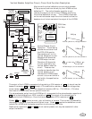
Monitors with vertical deflection current which exceeds
2.2 Ap-p cannot be driven directly by the LA7838 vertical
deflection IC. The vertical booster amplifier circuit
reduces the output current of the LA7838 by amplifying
the vertical deflection current. The LA7838 is mounted
on the vertical booster amplifier circuit board to allow the
boosters circuit to be inserted at the output of the LA7838.
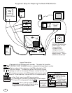
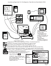
Vertical Booster Amplifier Circuit, Circuit And Function Description.
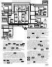
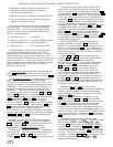
Vertical Booster Circuit,
Operation. The following
waveforms are taken from
the 2793-VGA monitor.
See waveform #1 for the
vertical deflection current.
Waveform #2 shows the
LA7838 output current.
Waveform #3 shows the
current supplied by the
vertical booster amplifier
circuit. These current
waveforms describe how the
vertical booster circuit
reduces the LA7838 output
current to a current which is
well within the specification
of the IC.
Vertical yoke drive, voltage waveform.
Vertical yoke drive, current waveform.
LA7838 output, current waveform.
44Vp-p
3.0Ap-p
0.6Ap-p
2.4Ap-p
Vertical booster, current waveform.
#1
#3
#2
#2
#3
#1
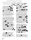
YC1
YC2
449
2,200uF
385
.68Ω
+
Vertical
Deflection
Yoke
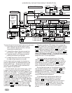
The retrace booster pulse, from the LA7838 pin 9, is connected to the retrace booster capacitor at
380 and is also buffered by an NPN transistor at 602 . The output of the retrace boost is
connected to the LA7838 at pin 13 and to the vertical booster NPN transistor at
603 .
Diodes 604 and 611 conduct current, right at the start of retrace. This current is produced by
the energy in the yoke, from the end of the last trace. Diode 382 supplies the deflection current
to both the LA7838 and the booster amplifier circuits during trace time.
Stabilization capacitors 606 and 609 are not used at present, but may be needed with other
output transistors.
610
601 603
610
380
604
382
603
602
611
606
609
87