


4
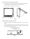
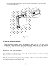
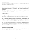
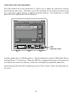
3) Remove the touchscreen assembly from the backbox
a. Remove the two screws as shown in Figure 3 (DO NOT REMOVE THE SCREWS
ON THE GREEN CIRCUIT BOARD). Retain screws for reassembly.
b. Remove the touchscreen assembly as shown in Figure 3.
Figure 3
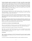
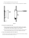
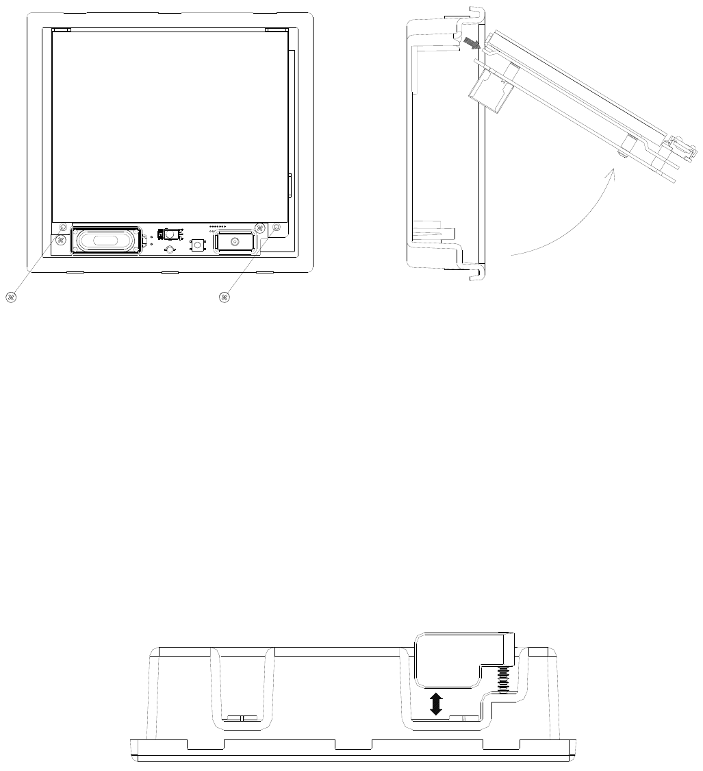
4) Install the backbox into the cutout in the wall
a. Insert the communications cable through the rectangular cutout in the touchscreen
backbox.
b. Locate the retaining flange screws in the upper right and lower left corners. Turn the
screws counterclockwise until the gap between the retaining flange and the housing
flange is wider then the wall (see Figure 4).
TOUCHSCREEN BACKBOX
TOP VIEW
Figure 4