


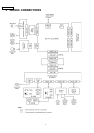
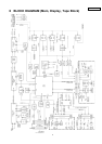
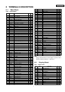

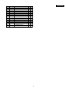
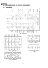
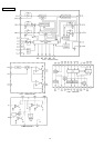
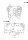
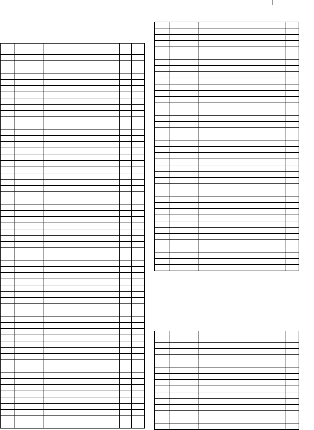
8.1. Main Block
IC601 : C2CBHG000077
Pin
No.
Port Description I/O (V)
1 BEEP Beep output O 0
2 IDC-ST/SP CD.C start/stop O 4.9
3 EVOL CLK Electronic volume clock O 0
4 EVOL DATA Electronic volume data O 0
5 SEC-LED Security LED on/off O 4.9
6 VOL A Rotary encoder data I 0.5
7 VOL B Rotary encoder data I 0.5
8 LCD-CLK Shift clock for LCD data O 0
9 LCD-DI LCD data O 5.0
10 LCD-DO LCD data I 0
11 RESET Reset input I 4.9
12 XT2 Crystal oscillator terminal - 2.4
13 XT1 Crystal oscillator terminal - 0.7
14 VSS Ground - 0
15 X2 Crystal oscillator terminal - 2.3
16 X1 Crystal oscillator terminal - 1.8
17 REGOFF (Connecting to VDD) - 4.9
18 REGC (Connecting to VDD) - 4.9
19 VDD +5V power supply - 4.9
20 VOL C Rotary encoder data I 4.8
21 VOL D Rotary encoder data I 0.5
22 LCD-CE LCD driver enable O 0
23 BOSE (Connecting to ground) - 0
24 SEC-CS Security ROM chip select O 0
25 SEC-CLK Data shift clock for security ROM O 0
26 SEC-DI Security data I 0
27 SEC-DO Security data O 0
28 SET-SEC1 (Ground pull-down) - 0
29 SET-TIME2 (Vdd pull-up) - 4.9
30 SET-TIME (Vdd pull-up) - 4.9
31 P.CONT COM8V power switch O 4.8
32 ACC CNT ACC 5V power switch O 4.9
33 STB Power amp. Stand-by O 4.9
34 LCD ON LCD illumi. on/off O 4.9
35 TUNER +B Motor antenna power O 4.9
36 PLL-CE PLL chip select O 0
37 PLL-DO PLL data O 0
38 PLL-CLK Shift clock for PLL data O 0
39 PLL-DI PLL data I 5.0
40 VSS Ground - 0
41 VDD +5V power supply - 4.9
42 AREA (Ground pull-down) - 0
43 ST-IND FM stereo detection I 0.3
44 CA.PON Tape power control O 4.9
45 CM.PON Tape power control O 4.9
46 M2 Main motor control O 0
47 M1A Loading motor control O 0
48 M1B Loading motor control O 0
49 T.IN Tape-in detection I 0
50 MSM MS gain contrl O 4.9
51 A/B Tape side detection I 0
52 M2F Main motor control O 0
53 EQ(MTL) Metal tape mode selection O 4.9
54 F/R Tape head change O 0
55 DOLBY Dolby NR on/off O 4.9
56 T.LOAD Tape loading detection I 0
57 MS(PL/FF) MS mode selection O 0
58 MS MS detection I 0
59 REMO3/4 (Ground pull-down) - 0
60 H.BUSOUT Not used - -
61 NAVI-IN (Vdd pull-up) - 4.8
62 NC No connection - -
63 NC No connection - -
64 NAVI-MUTE Not used - -
65 BIT1 Tape mode switch I 4.6
66 END.A Tape end signal I 1.5
67 END.B Tape end signal I 2.4
68 BIT2 Tape mode switch I 4.6
69 EQ Metal/Normal switchl I 0
70 BIT3 Tape mode switch I 0
71 NC No connection - -
72 NC No connection - -
73 IC/VPP (Connecting to ground) - 0
74 REMO Remote control signal O 5.0
75 SW.A Audio signal switch O 0
76 SW.B Audio signal switch O 0
77 MUTE Not used - -
78 NC No connection - -
79 NC No connection - -
80 VSM Phase diff. level detection I 0.6
81 AMP MUTE Power amp mute O 0
82 AVDD +5V power supply - 4.9
83 AVREF1 Analog reference voltage I 5.0
84 AVSS Ground - 0
85 NC (Connecting to ground) - 0
86 NC No connection - -
87 ACC-DET ACC level detection I 4.5
88 TAPE EJ Tape eject SW I 4.6
89 H.BUS.IN Not used - 4.8
90 GAIN (+5V pull-up) - 4.8
91 IDCEJECT CD disc eject SW I 4.7
92 BAT-DET Battery level detection I 4.5
93 EJ.INH Tape/Disc eject SW I 4.4
94 IDC-SI CD.C serial data O 4.0
95 RXO Not used - 0
96 TXO Not used - 4.9
97 IDC-CLK Shift clock for CD.C data O 4.9
98 IDC-SO CD.C data O 1.2
99 CD-RESET CD.C reset O 4.9
100 CDON CD.C controller enable O 4.9
Note :
Voltage measuerments are with respect to ground, with a
voltmeter (Internal resistance : 10M ohms.)
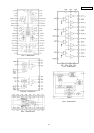
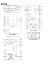
8.2. Display Block
IC901 : YEAMLC75853
Pin
No.
Port Description I/O (V)
1, 2 S1, 2 Disc LED on/off O 0
3 S3 Not used - -
4-40 S4-40 LCD segment data O 2.5
41-43 COM1-3 LCD common O 2.5
44 S41 LCD segment data O 2.5
45-49 KS2-6 Key strobe O 0.9
50-53 KI1-4 Key data I 0
54 KI5 (Connecting to ground) - 0
55 TEST (Connecting to ground) - 0
56 VDD +5V power supply - 5.1
57 VDD1 LCD angle - 3.3
58 VDD2 LCD angle - 1.7
59 VSS Ground - 0
60 OSC Oscillator terminal - 3.9
8 TERMINALS DESCRIPTION
7
HONDA / CQ-EH8160AK