


3
INSTALLATION
POWER CONNECTIONS
The CS amplifiers require a reliable
connection to the vehicle’s electrical
system in order to perform optimally.
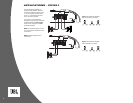
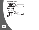
See Figures 1, 2 and 3 for terminal
connection locations. Please adhere
to the following instructions carefully:
Ground Connection
Connect the amplifier’s Ground (GND)
terminal to a solid point on the vehicle’s
metal chassis, as close to the amplifier
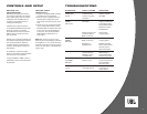
as possible. Refer to the wire gauge chart to
determine minimum wire gauge size. Sand
away any paint from this location; use a star-
type-lock washer to secure the connection.
Power Connection
Connect a wire (see chart at right for
appropriate gauge) directly to the vehicle’s
positive battery terminal, and install an
appropriate fuse holder within 18" of the
battery terminal.
Do not install the fuse at
this time.
Route the wire to the amplifier’s
location, and connect it to the amplifier’s
Positive (+12V) terminal. Be sure to use
appropriate grommets whenever routing
wires through the firewall or other sheet
metal.
Failure to adequately protect the
positive wire from potential damage may
result in a vehicle fire. When you are done
routing and connecting this wire, you may
install the fuse at the battery.
Remote Connection
Connect the amplifier’s Remote (REM)
terminal to the source unit’s Remote Turn-
On lead using a minimum of 18-gauge wire.
NOTE: If your source unit does not have a
remote turn-on connection, connect the
amplifier’s (REM) terminal to the vehicle’s
accessory circuit.
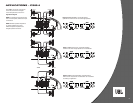
Speaker Connections
Refer to the application guides on the
pages that follow. Speaker connections
should be made using a minimum of
16-gauge wire.
Wire Gauge Chart
Amplifier Maximum Minimum
Model Current Draw Wire Gauge
CS60.2 22A #8 AWG
CS60.4 40A #8 AWG
CS300.1 42A #8 AWG
These recommendations assume 10' – 12'
wire runs. If your installation differs mark-
edly, you will need to adjust the wire gauge
accordingly.
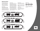
Figure 1. Terminal connection end plate for CS300.1.
Figure 3. Terminal connection end plate for CS60.2.
Figure 2. Terminal connection end plate for CS60.4.