


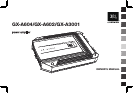
www.jbl.com
English
5
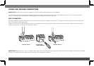
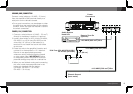
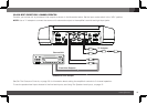
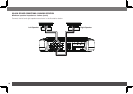
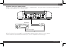
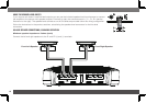
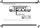
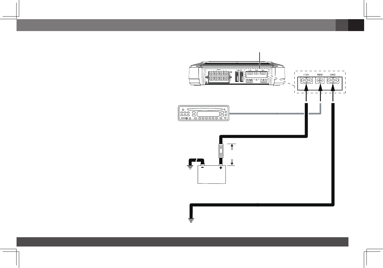
GROUND (GND) CONNECTION
Connectawire(minimum10AWG–5.3mm
2
)
from the amplifier’s GND terminal directly to a
solid point on the vehicle’s chassis.
•Foragoodconnection,usesandpapertoclear
the paint from the metal surface at this chassis
location. Use a star-type lock washer to secure
the wire’s connection.
POWER (12 V) CONNECTION
1.Connectawire(minimum10AWG–5.3mm
2
)
directlytothebattery’spositive(+)terminal.
2.Installafuseholderfora50Afuse(GX-A604,
GX-A3001)ora30Afuse(GX-A602)onthis
wirewithin18"(46cm)ofthebattery’s(+)
terminal. Do not install the fuse in the holder
at this time.
3. Route this wire to the amplifier’s location and
connectittotheamplifier’s+12Vterminal.
Be sure to use appropriate grommets
whenever routing wires through the firewall
or other sheet metal. IMPORTANT: Failure
to adequately protect the positive wire from
potential damage may result in a vehicle fire.
4.Whenyouarefinishedroutingandconnecting
this wire, install the appropriate fuse in the
holder you installed near the battery.
(GX-A604,GX-A3001–50Afuse;
GX-A602–30Afuse)
Power
Connectors
Audio System
Head Unit
Chassis Ground
(bare metal)
50 A Fuse (GX-A604/GX-A3001)
30 A Fuse (GX-A602)
18" (46 cm)
Remote Turn-On
(optional)
>#18 AWG (0.82 mm
2
) Wire
>#10 AWG (5.26 mm
2
) Wire
>#10 AWG (5.26 mm
2
) Wire