


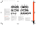
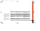

3. If you are running either the P-7520 or
the P-7540 in tri-mode (stereo and
mono simultaneously to one or two
pairs of satellite speakers and a sub-
woofer), refer to the chart above to
determine the capacitor and inductor
values you’ll need to route bass sig-
nals to the woofer, and midrange and
high frequencies to the satellite speak-
ers. These passive-crossover compo-
nents will also ensure that the imped-
ance of the speaker system doesn’t
drop below 2 ohms. The P-2510 should
be used to drive woofers only as its
bandwidth is limited to 20Hz – 320Hz.
Wiring the Input Connections
1. If you are using conventional RCA
input connections and a source unit
with output voltage less than 4V, sim-
ply plug the RCA plugs into the RCA
jacks on the amplifier.
4
Mounting the Amplifier
The JBL P-7520, P-7540 or P-2510 can be
mounted in virtually any location inside
the vehicle. However, make sure to keep
the amplifier away from heater vents or
ducts.
1. At the chosen site, use the amplifier as
a mounting template and mark the
locations of the four mounting holes.
2. Drill a small pilot hole at each marked
location.
3. Mount the amplifier and securely
tighten the mounting screws.
Wiring the Speaker Output
Connections
1. Connect the speakers, observing prop-
er polarity, to the speaker-output barri-
er strip on the amplifier using at least
16G high-quality speaker wire. (Note:
The total impedance of the speakers
connected to the outputs when the
amp is driven in stereo must be at
least 2 ohms. Because the P-2510 is a
single-channel amplifier, the speaker
connections on the barrier strip are
wired in parallel inside the amp. The
total impedance of the speakers con-
nected to the P-2510 must be at least 2
ohms.)
2. If you are bridging the amplifier, con-
nect the speaker wires to the termi-
nals marked “bridge,” observing prop-
er polarity. (Note: The total impedance
of the speaker system to be connected
to the amplifier must be at least 4
ohms in bridge mode.)
FREQUENCY INDUCTOR CAPACITOR
Crossover 6dB/oct. LP 6dB/oct. HP
(4 ohm) (4 ohm)
75Hz 8.0mH 530µF
100Hz 6.4mH 400µF
125Hz 5.0mH 318µF
150Hz 4.2mH 265µF
175Hz 3.6mH 227µF
200Hz 3.2mH 198µF
40
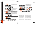
+ + – –
MADE IN THE U.S.A.
SPEAKER OUTPUTS
FUSE
40A
+
BATT REM GND
POWER
+R–
+R–
–L+
–L+
R
L
FRONT
FRONT
REAR
LINE LEVEL
INPUT
UNIVERSAL INTERFACE
REAR
LEVEL
FREQ
4V .250V 32Hz
80Hz
320Hz
2V
8
1
2
4
6
12
5
P-2510
Wiring the Power Connections
Refer to diagrams on pages 3 and 4 for
connector locations.
1. For power, remote and speaker wires,
strip 1⁄4" off one end of each jacket to
reveal bare wire for insertion into the
barrier strip connectors.
2. Locate the 3-connection barrier strip
labeled +Batt, Rem and Gnd. Connect a
black wire (at least 10G) to the Gnd ter-
minal and connect the other end to the
nearest bare-metal chassis component.
Then, connect a red wire (at least 10G)
from the vehicle’s +12-volt battery
terminal to the +Batt terminal on the
barrier strip. Finally, connect a blue
wire (16G) to the Rem terminal on the
barrier strip and connect the other end
to the Rem output of the source unit.
If you are using speaker-level inputs
and speaker-level outputs from the
source, disregard the previous instruc-
tion regarding the Rem terminal.
P-7520/7540/2510 OM copy 7/14/98 11:46 AM Page 4