


5
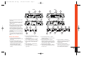
2. If you are connecting the amplifier to
a factory-installed source unit, or to a
source unit that only has speaker-level
outputs, connect the speaker outputs
of the source to the speaker inputs on
the amp, observing the following
color-code:
Front Left+: White
Front Left–: White with black stripe
Front Right+: Gray
Front Right–: Gray with black stripe
Rear Left+: Green
Rear Left–: Green with black stripe
Rear Right+: Purple
Rear Right–: Purple with black stripe
(Note: When using the Universal
Interface speaker-level inputs and
speaker-level outputs, the Rem termi-
nal on the amplifier may be used as a
remote output connection and will
provide power to turn on other ampli-
fiers and processors in the system.)
(Note: The front and rear inputs on the
P-2510 are summed to mono inside the
amp, and will provide constant bass
regardless of the position of source
unit balance and fader controls.)
3. If you are connecting your Power
Series amplifier to a source unit with
output voltage higher than 4V, connect
the output signal wires of the source
unit to the Universal Interface speaker
inputs. Because the inputs have an
impedance of 10K ohms, this connec-
tion will provide the best noise-free
performance possible.
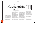
4. In some systems it may be desirable
to have two sources play simultane-
ously through the audio system.
For instance, if you have a factory-
installed radio in your car and you
want to add an aftermarket CD player,
you may connect the CD player to the
RCA inputs of the amp, and the facto-
ry radio to the Universal Interface
speaker inputs. (Note: Front and rear
channels of the CD and radio must be
driven into the front and rear inputs of
the amplifier. Use Y adapters if neces-
sary.) The Universal Interface circuitry
will isolate the two signals from each
other while allowing them to drive the
amp simultaneously. Therefore,
switching from one source to the
other is as simple as turning the
unused source off and the other on.
(Note: You must connect the remote
turn-on wire from the CD player to the
Rem terminal on the amp. Install a
diode in the remote line from the CD
player as shown in the diagram on
this page.)
System Setup and Adjustment
Electronic Crossover
The electronic crossover in the P-7520,
P-7540 and P-2510 should be used to
route the appropriate signal to speakers
intended to play only bass, midbass or
midrange and treble frequencies. The
crossover slope is 12dB/oct and the fre-
quency is variable from 32Hz – 320Hz.
Pre-amp Outputs
Connect these to the input connectors of
other amplifiers or processors in your
system.
The crossover-selector switch determines
which filter will be assigned to the pre-
amp outputs. The pre-amp outputs may
be High Pass (switch set to HP), Low Pass
(switch set to LP) or unfiltered (switch set
to Flat). The crossover-frequency is deter-
mined by the crossover frequency control
and will be the same frequency as the
amplifier channels affected by that con-
trol.
Refer to the “Applications” section for
system expansion possibilities.
Setting Input Sensitivity
Proper input-sensitivity control settings
on Power Series amplifiers are critical to
ensure optimum performance, low noise
levels and maximum system reliability.
As a general rule, controls at the front
end of a system (source, equalizers and
other processors) should be set as high
as possible with the amplifier input sensi-
tivity set as low as possible while still
providing adequate volume levels. Using
a high signal level and a low sensitivity
setting will help keep background noise
in the system to a minimum.
Initially, turn the input sensitivity GAIN
control to its minimum (counterclock-
wise) position (refer to Figure 9).
1. Reconnect the (–) negative lead to
your vehicle’s battery. Apply power to
the audio system and play a favorite
music track from CD or tape. (Note:
After the source unit is on, the JBL
badge (on the top panel) will illumi-
nate, indicating the amplifier is on. If
not, check the wiring, especially the
remote connection from the source
unit. Also refer to “Troubleshooting”
on the next page.)
2. On the source unit, increase the
volume control until it is approxi-
mately 3/4 of its maximum output
level. Slowly increase the Input
Sensitivity control (clockwise)
towards three o’clock and, at the
same time, listen to the quality of the
reproduced sound. At some point,
you’ll hear distortion on the music
peaks. Stop the adjustment and turn
it back slightly. This is the maximum
undistorted output level of your sys-
tem, and it should not be exceeded
during use.
From
Source
Unit
To
Amp
IN4001 Diode
P-7520/7540/2510 OM copy 7/14/98 11:46 AM Page 5